Overview
Sheet metal forming uses a variety of manufacturing processes to transform thin metal stock into durable and functional parts. Forming processes fall into two main categories: cutting operations (like shearing, blanking, and punching) and bending operations. The yield stress of the material must be exceeded to generate plastic strain and permanently deform the metal into the desired shape.
- Sheet metal thickness: 0.4 mm to 6 mm
- Common materials: low-carbon steel, aluminum, brass
- Advantages: inexpensive, lightweight, ductile, fast forming methods
Stress-Strain Curve
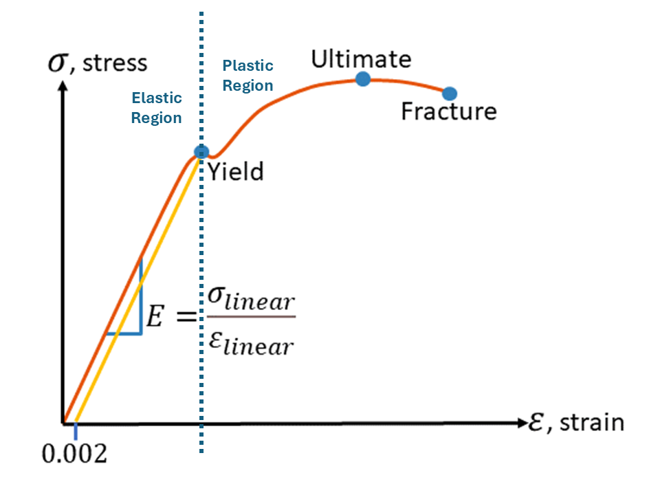
- Elastic Region: Reversible deformation; stress proportional to strain.
- Yield Point: Onset of plastic deformation due to dislocation movement.
- Plastic Region: Permanent deformation; strain hardening occurs.
- Ductility: Extent of plastic deformation before fracture.
- Toughness: Area under the stress-strain curve; energy absorbed before fracture.
Key Formulas
- Engineering Stress:
- \( P \) = applied load, \( A_0 \) = original area.
- Strain:
- \( \Delta l \) = change in length, \( l_0 \) = original length.
- Elastic Modulus: Ratio of stress to strain in elastic region.
Cutting Operations
- Shearing: Sheet metal cutting operation along a straight line between two cutting edges, typically used to cut large sheets
- Blanking: Sheet metal cutting to separate piece (called a blank) from surrounding stock
- Punching: Similar to blanking, but the cut piece is the scrap (called a slug)
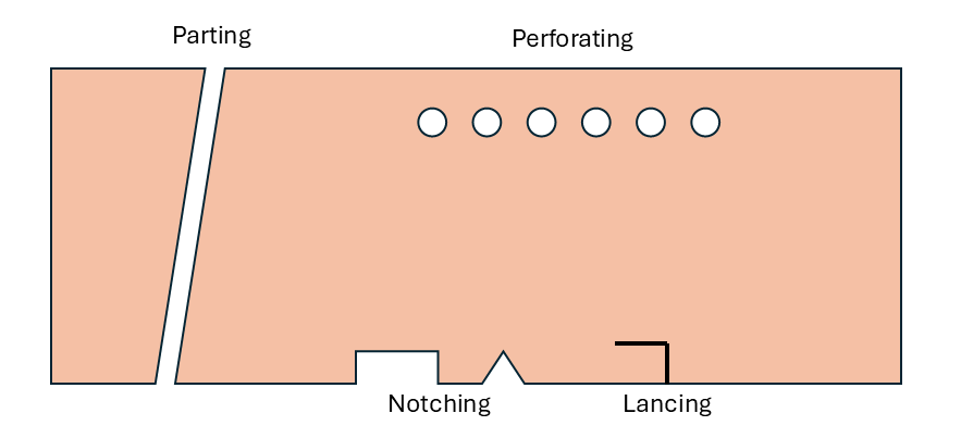
- Perforating: Punching a number of holes in a sheet
- Parting: Shearing the sheet into two or more pieces
- Notching: Removing pieces from edges
- Lancing: Producing a tab without removing any material
- If clearance too small, fracture lines pass each other, causing double burnishing and larger force
- If clearance too large, metal is pinched between cutting edges and excessive burr results
- Recommended clearance calculated by \( c = a \cdot t \), where \( a \) allowance depends on material.
- Angular clearance of 0.25°-1.5° for punching/blanking to allow slug or blank to drop through die
Clearance Summary
- where \( \tau_s \) = shear strength
- \( \sigma_{UTS} \) = Ultimate Tensile Strength
- t = stock thickness
- L = length of the cut (circumference of die, not punch)
Bending Mechanics
- V-bending: performed with a V-shaped die on a press brake
- V-dies are simple and inexpensive
- used for lower volume production
- Edge ("wipe") bending: performed with a wiping die, requires a pressure pad
- Wiping dies are more complicated and costly
- used for higher volume production
- Bending Force:
- L = length of part
- t = thickness of part
- \( \sigma_{UTS} \) = Ultimate Tensile Strength of part
- W = Width of die opening
- k = 1.25 for V-die, k = 0.32 for wiping die
- Example: \( \sigma_{UTS} = 275 \) MPa, \( L = 60 \) mm, \( t = 2 \) mm, \( W = 20 \) mm. \( k = 1.25 \)):
- Minimum Bending Radius (MBR) before cracking occurs is determined by the tensile strain-to-failure
- Outer fibers experience tension
- Inner fibers experience compression
- Bend Allowance \( L_b \) is the length of the arc along the neutral axis.
- If the bend radius is small relative to the stock thickness, metal will stretch during the bending.
- In order to make parts of the desired length, it is important to estimate the amount of stretching that will occur.
- (\( L_b \)): Length of arc along neutral axis.
Springback
After bending sheet metal, the part naturally recovers some of its original shape due to a finite Elastic Modulus (elastic recovery). To compensate, parts must be overbent, so the springback results in the desired angle.
- \( K_s \) = 1 means no springback
- \( K_s \) = 0 means complete recovery of original shape
- Springback Factor \( K_s \):
- Example: \( R_i = 20 \) mm, \( R_f = 20.9 \) mm, \( t = 2 \) mm:
Design Guidelines
- Use corner reliefs to prevent tearing
- Nest parts efficiently to reduce waste
- Maintain minimum hole sizes and spacing
- diameter greater than stock thickness T (\( > 2T \) for alloy or stainless steel)
- distance between holes \( > \) 2T
- Avoid holes near edges, corners, or bends
- distance from edge \( > \) T (1.5T preferred)
- distance from corner \( > \) H = 1.5T + bending radius
- Avoid sharp corners (Radii \( > \) 0.5T)
- Use generous bend radii to reduce springback