Intro
Spur gears transmit power between parallel shafts through sequential tooth contact. For proper operation, the ratio of angular velocities must match the ratio of the number of teeth, ensuring no slipping occurs. This also implies that torque and speed are inversely related, consistent with power transmission concepts from Machine Design.
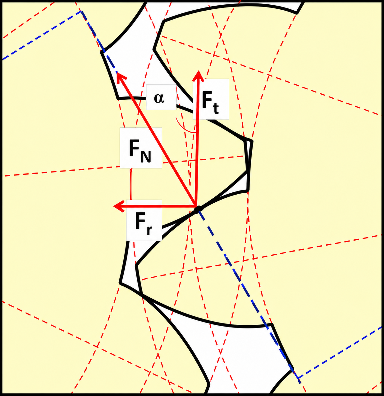
Key parameters include pitch, number of teeth, and pressure angle. The pressure angle determines the direction of the force between mating teeth and governs how the total force is split into tangential and radial components.

Spur Gears
The force between gear teeth acts along the line of action and can be resolved into:
- Tangential force \( F_t \) (transmits power)
- Radial force \( F_r \) (separates gears)
These are related by:
| Variable | Description | Typical SI Units | Typical Imperial Units |
|---|---|---|---|
| \( F_r \) | Radial force (separates gears) | N | lb |
| \( F_t \) | Tangential force (transmits power) | N | lb |
| \( \phi \) | Pressure angle | degrees | degrees |
Gear teeth can fail due to bending at the root and can be modeled as cantilever beams.
| Variable | Description | Typical SI Units | Typical Imperial Units |
|---|---|---|---|
| \( \sigma \) | Bending stress at tooth root | Pa | psi |
| \( F_t \) | Tangential force | N | lb |
| \( h \) | Tooth height (cantilever length) | m | in |
| \( b \) | Face width of gear | m | in |
| \( t \) | Tooth thickness at base | m | in |
The Lewis form factor \( Y \) simplifies this expression:
Imperial form :
Metric form :
| Variable | Description | Units |
|---|---|---|
| \( P \) | Diametral pitch | teeth/in |
| \( m \) | Module (\( m = 1/P \)) | mm/tooth |
The Lewis form factor \( Y \) accounts for tooth geometry and depends on the number of teeth and pressure angle. Larger numbers of teeth increase \( Y \), reducing bending stress. Typical values range from \( 0.2 < Y < 0.5 \).
A more refined stress model incorporates real-world effects:
Gear teeth experience cyclic loading, leading to fatigue failure at the root.
| Variable | Description | Typical SI Units | Typical Imperial Units |
|---|---|---|---|
| \( S_n \) | Modified endurance limit | Pa | psi |
| \( S_n' \) | Baseline endurance limit (\( \approx 0.5 S_u \)) | Pa | psi |
| \( C_L \) | Load factor | - | - |
| \( C_G \) | Gradient factor | - | - |
| \( C_s \) | Surface factor | - | - |
| \( k_r \) | Reliability factor | - | - |
| \( k_t \) | Temperature factor | - | - |
| \( k_{ms} \) | Mean stress factor | - | - |
Design Strategy
Gear design balances bending failure at the tooth root and surface (contact)fatigue. Increasing tooth size reduces bending stress, while case hardening improves surface strength. The tradeoff is governed by diametral pitch \( P \):
- \( P < 8 \) (coarse teeth): surface fatigue dominant
- \( P > 8 \) (fine teeth): bending failure dominant
Hardened steels allow smaller gears with higher strength and longer life,often reducing overall size and cost despite higher manufacturing difficulty.For compact design, begin with the minimum pinion size and solve for \( P \):
\( N \geq 18 \) (for 20 \( ^\circ \) pressure angle)Worm Gears
Worm gears are used for very high speed reductions (often \( >300:1 \)) in a compact space. A worm (screw-like shaft) drives a worm wheel with perpendicular axes.
One unique feature of worm hears is self-locking: for small lead angles, friction prevents back-driving, allowing loads to be held without additional braking.
 (1).jpg)
Worm Gear Forces
Unlike spur gears, worm gears have significant axial forces.
For a 90\( ^\circ \) configuration:
- Gear tangential force = Worm axial force
- Worm tangential force = Gear axial force
- Radial forces are equal
where \( \lambda \) is the lead angle.

Worm Gear Efficiency
Worm gears have lower efficiency due to sliding contact between surfaces.Efficiency depends on lead angle \( \lambda \) and friction:
- Larger \( \lambda \) \( \rightarrow \) higher efficiency
- Smaller \( \lambda \) \( \rightarrow \) more self-locking but lower efficiency
Efficiency can be expressed (from lecture notes) as a function of geometry and friction:
Efficiency decreases as friction increases and increases with lead angle.Typical efficiencies range from 50% to 90%. Self-locking occurs when friction is high enough that the gear cannot drive the worm.