Introduction to Springs
Springs are parts used to store energy, reduce impact, or control the positioning of mechanisms. There are many different types of springs, such as coil springs, Belleville springs, leaf springs, and gas springs.
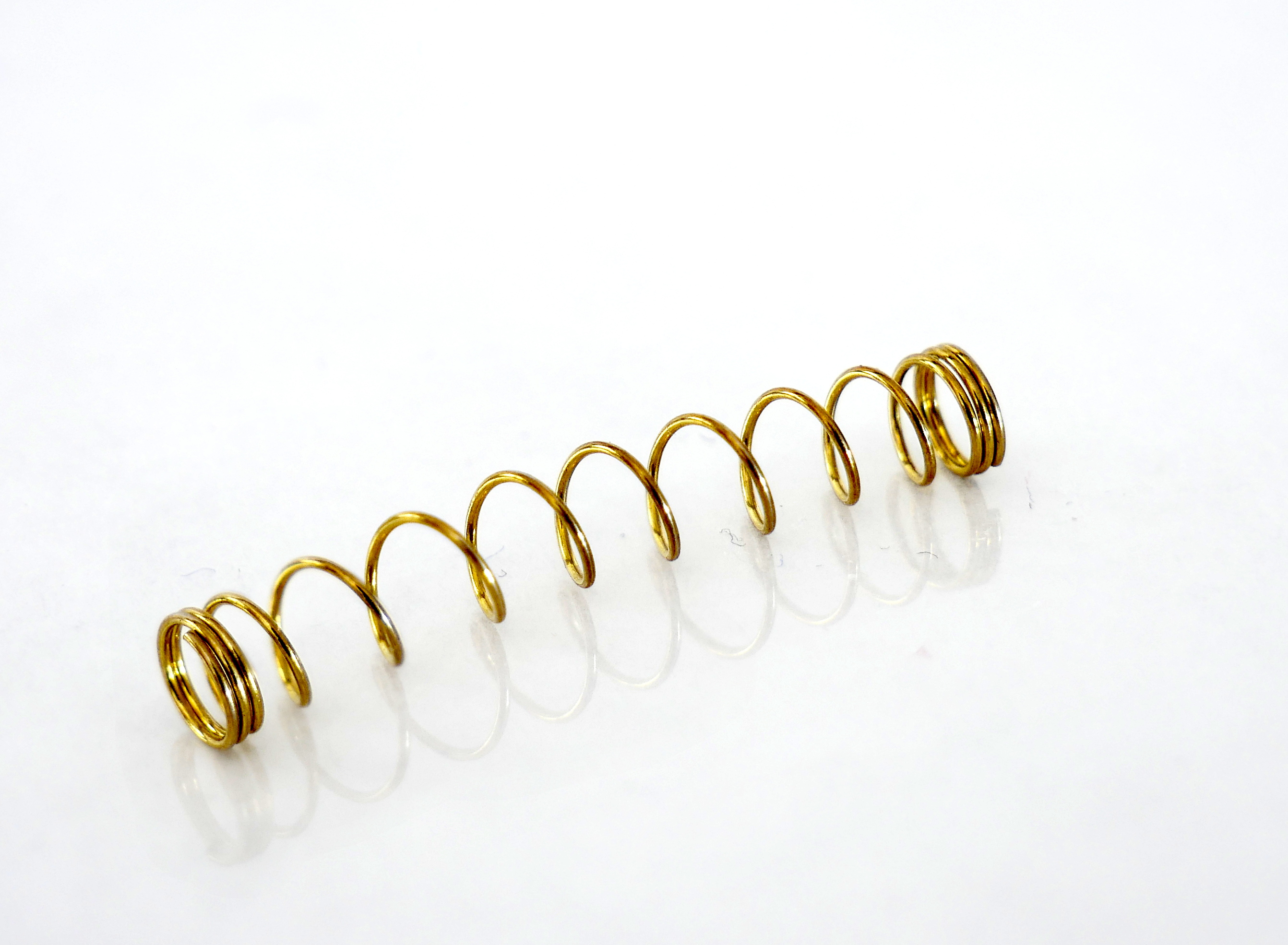
Most applications use coil springs, which employ the bending of coils to store energy. Coil springs can be designed to operate under tension, compression, or torsion.
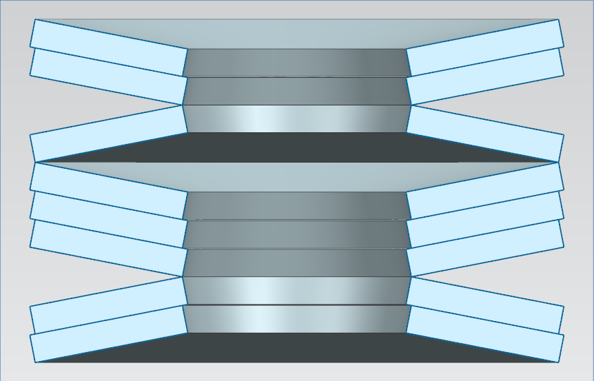
Belleville springs instead use the bending of stacked disks, and they are useful when high forces are required over a small deflection.
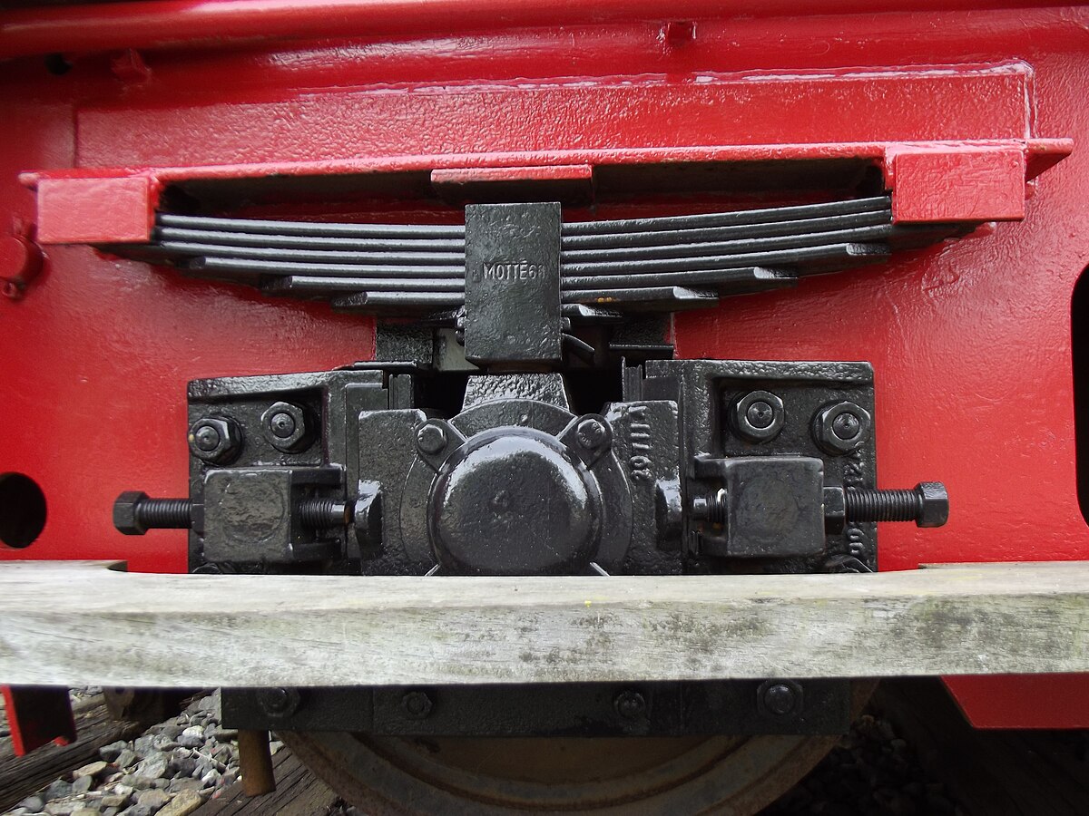
Leaf springs are made of stacks of long flat beams and are commonly seen in large vehicle suspension systems.
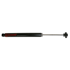
Gas springs do not use bending at all but instead store energy in pressurized air or other gases. These are most useful when smooth, controlled motion is required.
Stress in Springs
Let's take a look at the internal forces in a spring when a load is applied directly on its ends:
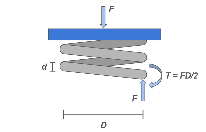
From this diagram we can observe that there is an axial force that comes from the external load on the spring and an upward reaction force through the wire. There is also a resulting internal moment that counteracts the couple generated by these two forces.
Each of these internal loads creates a component of shear stress, and the total stress is
where the first term is the torsional shear stress from the moment, and the second term is the pure shear from the upward reaction force.
We can rewrite this as
which can be solved completely with known dimensions and external load.
Static Loading, Fatigue, and Deflection
The shear stress equation can be simplified by introducing the spring index parameter \( C \), which is the ratio of the coil diameter to the spring diameter. We get the rewritten equation:
This new form frames the pure shear term as a correction factor \( K_s \).
As \( C \) becomes large, \( K_s \) approaches 1, and the torsion term dominates the pure shear term.
\bigskip
When we consider fatigue, we need a more accurate model that takes into account the impact of curvature on the spring. This leads us to the Wahl model, developed by A.M. Wahl. It replaces the spring correction factor with the Wahl factor \( K_w \), as shown in these two equations:
Finally, it is valuable to be able to compute the spring constant and the deflection of a spring based on the physical properties of the spring. To do this, we need to take into account several key parameters. In addition to the major diameter \( D \) the minor diameter \( d \), we also need to know the shear modulus of the material \( G \) and the number of active coils \( N \). deflection and spring constant are calculated with these expressions:
To clarify, active coils are coils that bend when a load is applied. Typically, there is an extra coil on each end of a spring that is passive, so with a total coil number \( N_t \), the active coil number follows
Solid Length
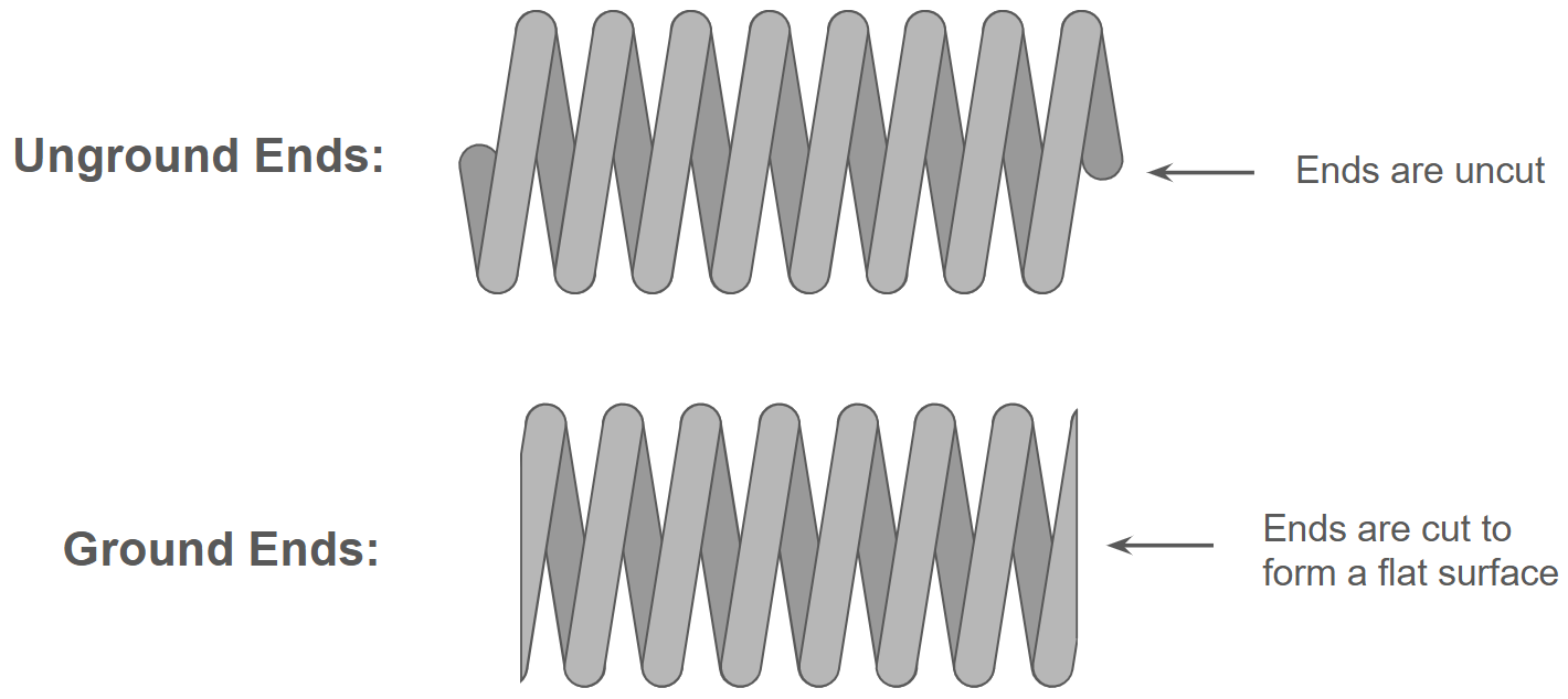
A spring's solid length is its length when it is fully compressed with no gaps between the coils. This length depends on whether the ends are ground or unground, i.e. whether they are cut to make each end flat or not.
For ground ends, the two passive coils add no extra length, so the solid length is simply the wire diameter \( d \) multiplied by the active coil number \( N \). For unground ends, the two end coils each stick out by half of their diameter, adding up to the diameter of one extra coil in total. So, for unground ends, the wire diameter is multiplied by \( N+1 \) rather than \( N \).
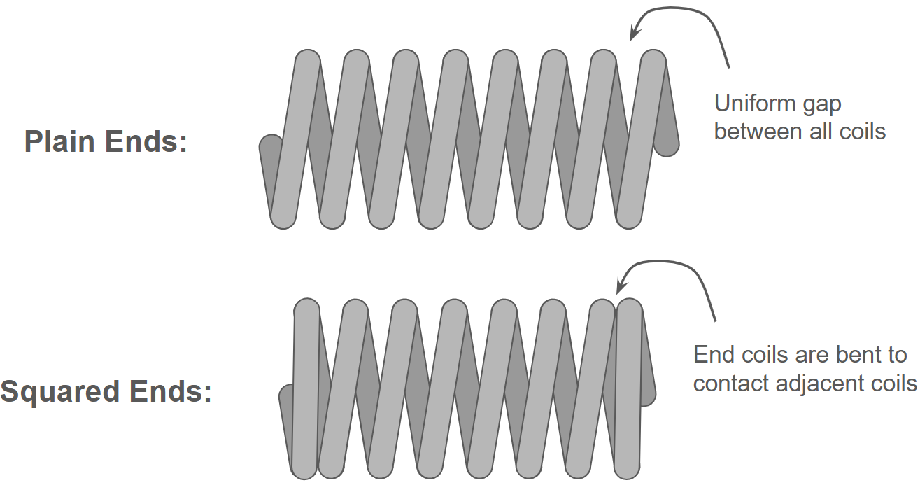
There is also another variation in end types: plain ends vs squared ends. Squared ends have the end coils in contact with the coils next to them, while plain ends leave space between the last two coils on each end.
| End Type | Unground | Ground |
|---|---|---|
| Plain |  | 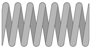 |
| Squared | 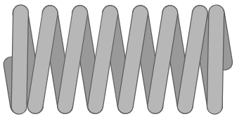 | 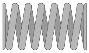 |
| Solid Length | \( (N_t+1)d \) | \( N_td \) |
Spring failure
Generally, there are 3 ways a spring can fail: clash, yield, and fatigue.
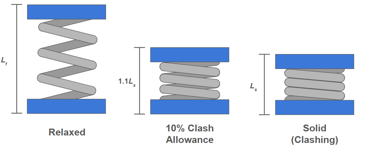
Clash is when a spring is compressed so far that the coils touch one another and the spring behaves like a solid cylinder. This impact force between coils can exert a lot of stress on them, causing wear on the coil edges and changing the effective spring constant.
Numerous factors such as thermal strain, tolerances, and damage make the exact clash point difficult to predict, so the standard practice to avoid clash is to design for a spring to be at least \( 10\% \)
| Condition | Criteria |
|---|---|
| Ferrous; Not Pre-set | \( \tau_s \leq 0.45S_u \) |
| Nonferrous; Not Pre-set | \( \tau_s \leq 0.35S_u \) |
| Ferrous; Pre-set | \( \tau_s \leq 0.65S_u \) |
| Nonferrous; Pre-set | \( \tau_s \leq 0.55S_u \) |
Fatigue involves failure from cyclic loading. To calculate fatigue stress, use the Wahl model shown in the prior section. Failure criteria depend on the number of loading cycles and the exact load setup, so the best guide is a constant-life fatigue diagram similar to a Goodman diagram. Here is an example of such a diagram for infinite life (over \( 10^6 \) cycles):
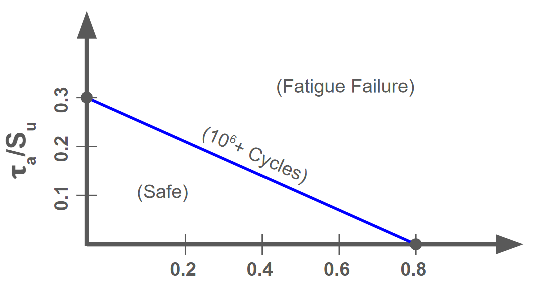
Keep in mind that for springs we must consider shear strength \( S_{us} \) rather than tensile strength \( S_u \). Shear strength can be easily approximated as: