Frames
Frames and machines are systems that contain at least one non two force member. This means that at least one member in a frame or machine has at least 3 loads applied to it. Unlike trusses, frames and machines are not necessarily only loaded at the joints, and are not necessarily compsed of long, slender members. Multi-force members in both frames and machines have the potential to have not only axial internal loads, but also shear internal forces and internal bending moments.
Frames are systems with at least one multi-force member that are generally designed to be stationary. Some examples of frames could be a children's playground or even a table.
Machines
Machines are systems with at least one multi-force member that have the potential to move. For example, an excavator is a machine.
Frame and machine analysis
Because frames and machines carry not only axial loads but also shear loads and bending moments, we can't use the method of joints or the method of sections to get internal forces. Instead, we need to "break apart" the pieces of the frame or machine and draw free body diagrams of each piece individually. Frame and machine analysis involves the following steps:
- Identify any two-force members and apply the two force member assumptions (see the Truss reference pages for more details)
- Identify any multi force members and make free body diagrams for each multi force member. When two connected members share a common force at their connection point, that force is equal in magnitude, but acts in the direction opposite of the direction it acts on the other member. This comes from Newton's third law, as this force is internal to the overall system.
- Use equations of equilibrium to solve for the unknown forces in the free body diagrams.

A ladder is a common example of an A-frame. An A-frame is a basic structure designed to bear loads in a lightweight economical manner. The simplest form of an A-frame is formed by joining two similarly sized beams at an angle of 45 degrees or less and additionally connecting them with a third horizontal beam, so that the structure looks like that of an uppercase letter "A."
Consider the simply supported A-frame shown below, which has a pin support at point \( A, \) a roller support at point \( E, \) and is supporting a vertical load \( P \) at the midpoint of line \( CD. \)
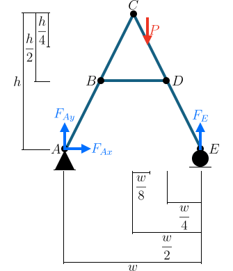
Free body diagrams for each member would like this.
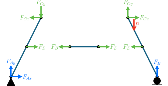
Take note that if a common force is shared between two free body diagrams, the force will be equal in magnitude, but act in the direction opposite of the direction it acts on the other member—this comes from Newton's third law. Equilibrium equations can then be written for each member to solve for the unknowns.
For this example, we are asked to find the internal force at point \( B \) on member \( ABC. \) Assume that point \( B \) is at the midpoint of member \( ABC \) and that point \( D \) is at the midpoint of member \( CDE. \) Assume that the structure is symmetrical.