Plastic Overview
Plastics are a wide range of synthetic materials made primarily of polymers. Their plasticity allow them to be manipulated in a variety of manufacturing methods, including molding, extrusion, and pressing. Their adaptability and wide range of properties has led to their widespread use across the globe.
[Add Diagram: Global plastic waste / recycling flow chart]
What are Polymers?
Polymers are long molecular chains formed by repeating smaller units called monomers.
Examples of monomers include ethylene, propylene, styrene, and vinyl chloride.
Polymerization is the chemical reaction that links monomers together.
[Add Diagram: Chain of monomers becoming polymer]
Thermoplastics
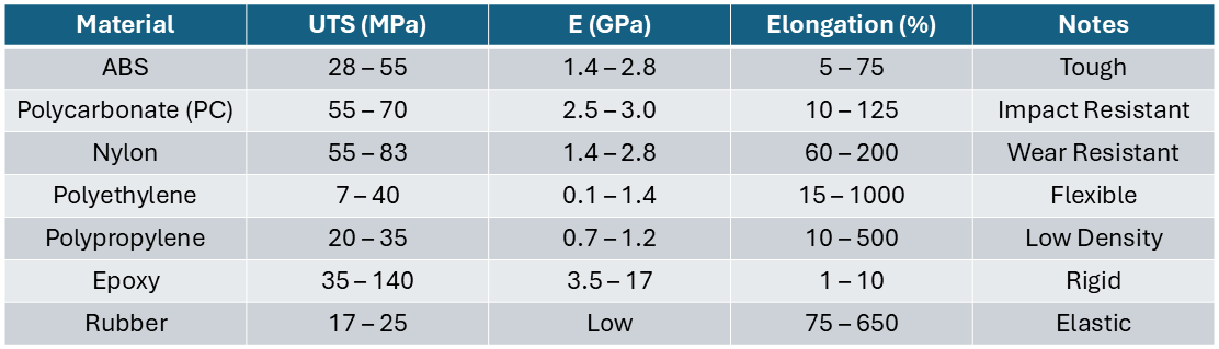
Thermoplastics are solid at room temperature but become viscous liquids when heated. Ex: ABS, Polycarbonate (PC), Polyethylene (PE), Polypropylene (PP), Nylon, PVC, PET
- Can be easily and economically shaped into products
- Melting can be done repeatedly
- Best for injection molding
- Can be welded or recycled
Applications: LEGO bricks, Water bottles, Electronic housings, Automotive trim
Thermosets
Thermosets can be molded during initial heating and mixing, but are permanently cured through cross-linking that activates in elevated temperatures. Ex: Epoxy, Phenolic, Polyester Resin, Polyimides
- Cannot be remelted- degrades and chars when reheated
- High temperature resistance
- High stiffness
Applications: Circuit boards, adhesives, handles, composites
Elastomers
Highly elastic polymers capable of large deformation. Ex: Rubber, Silicone, Neoprene, Urethane
- Some elastomers can be stretched by 10x and remain elastic
- Low modulus
- Used for seals and tires
[Add Diagram: Thermoplastic vs Thermoset vs Elastomer molecular structure]
Important Polymer Temperatures
-
Glass Transition Temperature (\( T_g \)): Polymer changes from hard/glassy to rubbery.
-
Above \( T_g \), stiffness may drop by 100-1000\( \times \).
-
Melting Temperature (\( T_m \)): Crystalline regions melt into viscous liquid.
-
Processing Temperature: Temperature used during molding.
[Add Graph: Modulus vs Temperature showing \( T_g \) and \( T_m \)]
Additives
Used to modify plastic behavior:
- Fillers — strengthen or lower cost
- Plasticizers — soften material and improve flow
- Colorants — pigments or dyes
- Flame retardants — reduce flammability
- Lubricants — reduce friction and improve flow
- UV stabilizers — reduce sunlight degradation
- Antioxidants — reduce oxidation damage
- Cross-linking Agents — for thermosets and elastomers
- Fibers (glass/carbon) — reinforcement
Recycling Codes
- PET
- HDPE
- PVC
- LDPE
- PP
- PS
- Other
Best commonly recycled: PET and HDPE
[Add Diagram: Recycling triangle symbols 1--7]
Injection Molding
Injection molding is the most common manufacturing process for thermoplastic mass production. It is similar to high-pressure metal die casting-- pellets of thermoplastic are heated and forced into a split-die chamber.
Similar to high-pressure die metal casting, there is a feed system to deliver the melted plastic to the cavities. The cavity is filled with many small, narrow openings called gates.
Examples:
- LEGO bricks
- Bottle caps
- Keyboard keys
- Medical syringes
- Consumer product housings
Method
Plastic pellets are fed into a heated barrel where a rotating screw:
- conveys pellets forward
- melts material using heat + shear
- meters the required shot volume
- injects melt into mold cavity
Then the plastic cools, solidifies, and is ejected.
[Add Diagram: Injection molding machine labeled hopper, barrel, screw, nozzle, mold]
Cycle Steps
- Mold closes
- Screw moves forward and injects melt into cavity
- Packing / holding pressure applied
- Cooling begins
- Screw retracts and prepares next shot
- Mold opens
- Ejector pins remove part
Typical cycle time: 5-60s depending on part thickness.
[Add Diagram: 6-step cycle illustration]
Terms
- Sprue: Main channel from nozzle
- Runner: Horizontal flow channel
- Gate: Small opening into part cavity
- Parting Line: Separation between mold halves
- Ejector Pins: Push part out
- Core/Cavity: Internal and external mold surfaces
[Add Diagram: Mold feed system showing sprue, runner, gate]
Cooling Time
Cooling is often 50-70% of the total cycle time
- Note the quadratic dependency on \( d \), meaning:
- Thick walls cool much slower
- Thin walls reduce cycle time
- Uniform walls reduce warpage
- \( a = \frac{\gamma}{\rho c} \) is thermal diffusivity \( [\frac{m^2}{s}] \)
- \( T_p > T_e > T_d \) (melt processing, ejection, and mold wall temperatures)
Clamp Force
The mold must withstand large pressures without deformation, with a typical lifetime of 1 million "shots". The mold halves are pushed together with a clamping pressure of \( 70 - 200 \) MPa. Machine must hold mold shut against cavity pressure with a clamping force:
where:
- \( F \) = clamp force
- \( P \) = cavity pressure
- \( A \) = projected area
Too little of a clamp force causes flash formation, so molders often use more than the above force.
Cost Drivers
Tooling Cost:
- highly dependent on mold complexity and environment (temperature, pressure, cycle speed)
- Dominates at low production volume
Processing Cost:
- highly dependent on cycle time- longer cycles have higher labor/overhead per part
- Thicker parts take longer to cool— \( t_{cool} \propto d^2 \)
Material Cost:
- Entirely variable
- Dominates at high production volume
Common Defects
- Flash — excess plastic at mold parting line
- Witness marks — contact from ejector pins
- Sink marks — depressions over thick sections
- Warpage — uneven shrinkage
- Short shot — incomplete fill
- Weld lines — two flow fronts meet
- Burn marks — trapped gas overheats
- Flow lines — visible flow patterns
[Add Image Grid: examples of common defects]
Design Guidelines
- Use uniform wall thickness
- Add ribs instead of thick solid walls (parallel to material flow)
- Use multi-cavity molds for high volume
- Include draft angle (1-3\( ^\circ \) minimum)
- Round corners and avoid undercuts entirely, if possible
- Place gates in thick sections
- Bosses can be used like cylindrical ribs to prevent air entrapment and avoid thickness variations
[Add Diagram: Good vs bad wall thickness design]
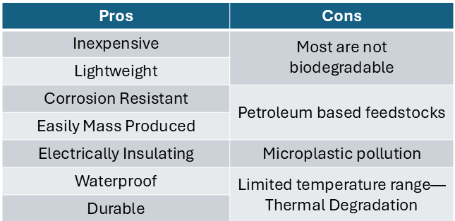
Plastic Product Properties:
- Strength and Stiffness — generally not as good as metals
- Strength/Weight Ratio — competitive with metals
- Creep — problem for thermoplastics, not for thermosets
- Temperature Range — limited relative to metals and ceramics
- UV protection needed to prevent sunlight degradation
- Absorbs impacts well
- Often soluble; resistant to most acids and bases
Types of Molds
- Two-plate mold
- Three-plate mold
- Hot-runner mold
- Multi-cavity mold
- Family mold
Hot runner advantage: less scrap, faster cycles.
[Add Diagram: Two-plate vs three-plate vs hot-runner]
Other Plastic Processes
- Extrusion — pipes, tubing
- Blow molding — bottles
- Compression molding — thermosets
- Reaction Injection Molding (RIM)
- Structural Foam Molding (SFM)
- Vacuum Forming/Thermoforming
- Rotomolding — hollow tanks