Overview
- Joining is the process of putting together two or more parts.
- Welding (metals and plastics)
- Brazing and Soldering (certain metals)
- Adhesive Bonding (nearly all materials)
- Mechanical Fastening (nearly all materials)
- Joining using Interface Fit/Snap Fit (nearly all materials)
- Assembly is the sequence multiple joining operations involved in making a product
Welding
- Fusion: Material is melted and joined on solidification. Ex: Oxyfuel, Arc
- Solid State: Does not melt material. Ex: Friction Welding, Electrical Resistance
Fusion Welding
Oxyacetylene gas welding (OAW, or Oxyfuel Welding) is the most common gas welding process. It is typically used for structural metal fabrication and repair work. Arc welding uses a power supply to create an electric arc between a metal stick ("electrode") and the base material to melt the metals on contact. Both consumable and non-consumable electrodes can be used.
Arc Welding Power
where \( H \) = heat input, \( l \) = weld length, \( e \) = efficiency (0.75 - 0.9), \( V \) = voltage, \( I \) = current, and \( v \) = welding speed.
Types of Arc Welding:- GTAW- Gas Tungsten Arc Welding (TIG- Tungsten Inert Gas)
- SMAW- Shielded Metal Arc Welding (Stick)
- SAW- Submerged Arc Welding
- GMAW- Gas Metal Arc Welding (MIG- Metal Inert Gas)
- FCAW- Flux Core Arc Welding
- PAW- Plasma Arc Welding
- EGW- electrogas welding
- ESW- electroslag welding`
Non-Consumable Electrode: TIG Welding
- Uses tungsten electrode to supply heat via electric arc
- Wire is used as weld filler
- Shielding gas (typically argon-helium mixture) is needed to prevent oxidation
- AC or DC current can be used, depending on the metal
- Well-suited for thin sheets or tubes of Al, Mg, and Ti
Consumable Electrode: MIG Welding
- MIG, or Gas Metal Arc, is a variant of TIG used for steels
- The filler wire is consumed and doubles as the electrode
- Shielding gas is still needed, and both AC or DC current can be used
Solid State Welding
Friction welding is done by rubbing two parts together under high pressure, allowing the surface to soften and fuse without melting. This does not require filling, and the bond can be created between both similar and dissimilar materials. It is used with metals and thermoplastics.
add image
Electrical Resistance Welding, or Spot Welding, joins two parts by heating them with an electric current and melting the metal at the joint.
where \( H \) = Heat, \( I \) = Current, \( V \) = Voltage, \( t \) = time, and \( k \) = compensation factor for heat loss to conduction and radiation (unitless).
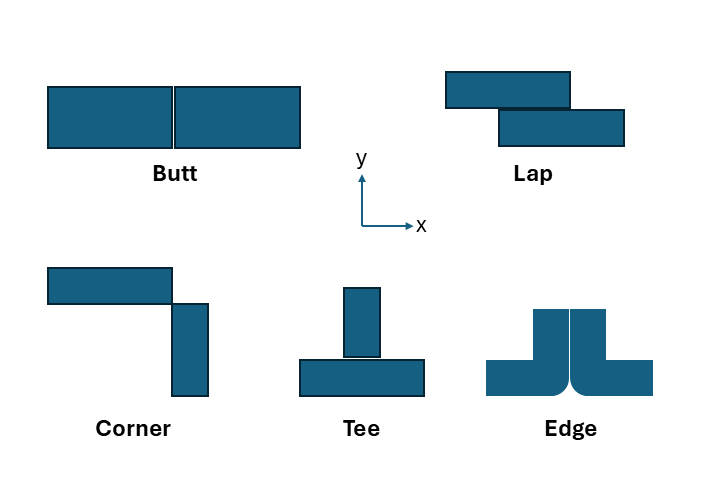
Types of Welding Joints
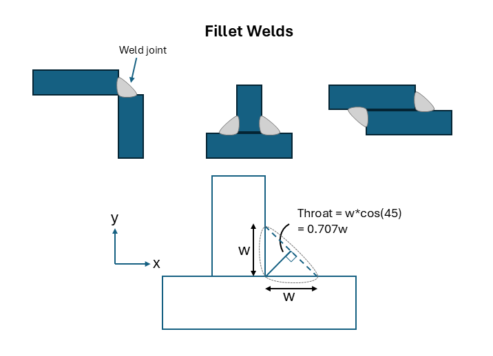
Failure plane is along the Throat
Strength of Fillet Welds:
where \( \sigma_v \) = shear stress, F = applied force, w = fillet dimension, and L = weld length
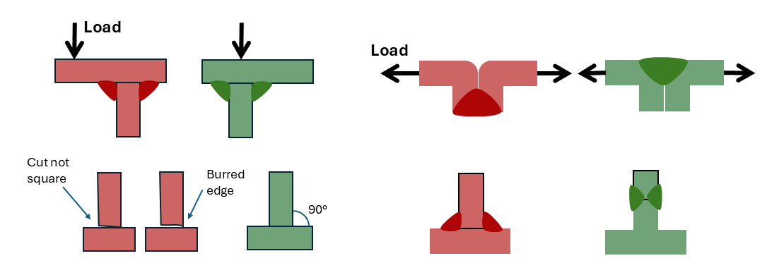
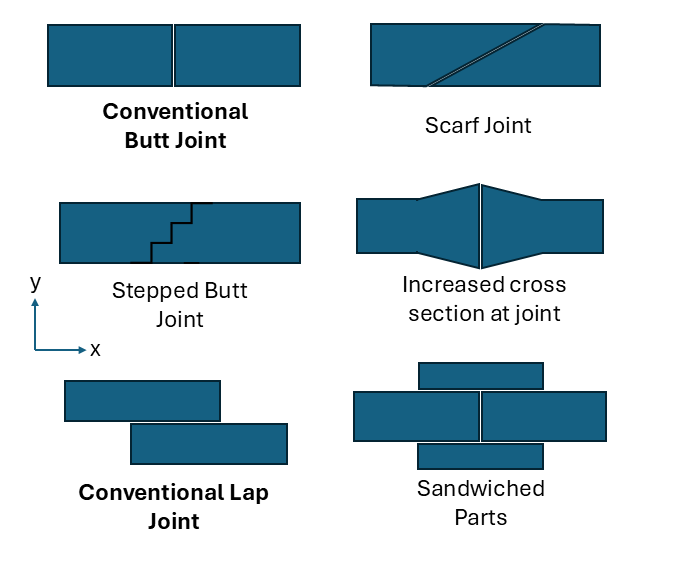
Joint Design for Welding
Brazing and Soldering
A filler metal, typically supplied by a wire, is applied to the parts being joined. The parts are then heated, melting the filler metal and allowing it to spread over the joint surface area via capillary forces.
- Soldering is done \( < 450^\circ \)C with tin-bearing alloys
- Brazing is done \( > 450^\circ \) C for copper alloys and other metals
- Joint surfaces must be very clean for effective filler flow. Flux can be applied before the process to remove oxides (flux fumes are toxic, so good ventilation is required)
- Maximizing contact surface area improves joint strength
Joint Design for Brazing
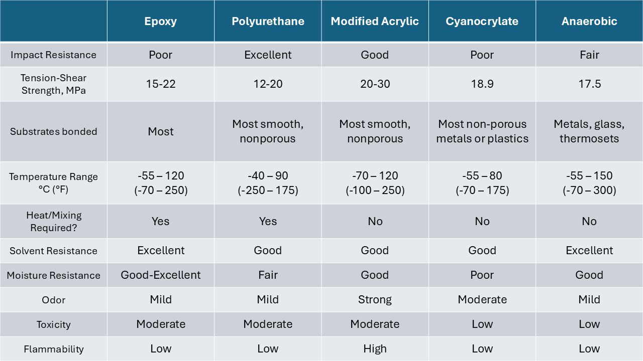
Adhesives
- Epoxy Based Systems: high strength and temperature properties (up to 475 K).
- Acrylics: Suitable for contaminated or unclean surfaces
- Anaerobic Systems: Adhesives with oxygen deprivation, typically forms a hard and brittle bond. Curing times can be improved by external heating or UV radiation.
- Cyanoacrylate: The bond lines are thin and sets within 5-40s (superglue!)
- Urethanes: High toughness and flexibility at room temperature, often used as sealants
- Silicones: Highly resistant to moisture and solvents, high impact and peel strength. Curing times are usually 1-5 days.
- These are all Polymers!
- Maximize Surface Area when designing joints
Content adapted from S. Kalpakjian and S. R. Schmid, Manufacturing Engineering and Technology
Mechanical Fasteners
Joining of parts using a separate component relying on mechanical forces. These can be removeable (like bolts and screws) or permanent (like rivets)
Bolt Strength
Means of bolt failure:
- Stripping of external threads
- Stripping of internal threads
- Excessive tensile strength in cross-sectional area
Bolt tensile stress:
where \( F \) = maximum load and \( A_s \) = cross sectional area
- metric(ISO): \( A_s = (\pi/4)(D-.9382p)^2 \) where D = diameter, p = pitch
- ANSI: \( A_s = (\pi/4)(D - 0.9743/n)^2 \) where D = diameter, n = threads/inch
Connection Strength
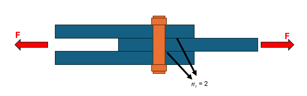
Bearing Type:
- \( R_n \) = Resistance
- \( F_v \) = Material shear strength
- \( A_b \) = Bolt cross sectionl area
- \( n_s \) = number of shear planes
Slip Critical Type:
- \( R_n \) = Resistance
- \( \mu \) = Friction coefficient
- \( T_n \) = Bolt tension
- \( n_s \) = number of shear planes
Types of Threaded Fasteners
Bolts thread into a (non-affixed) nut whereas screws go into a threaded hole
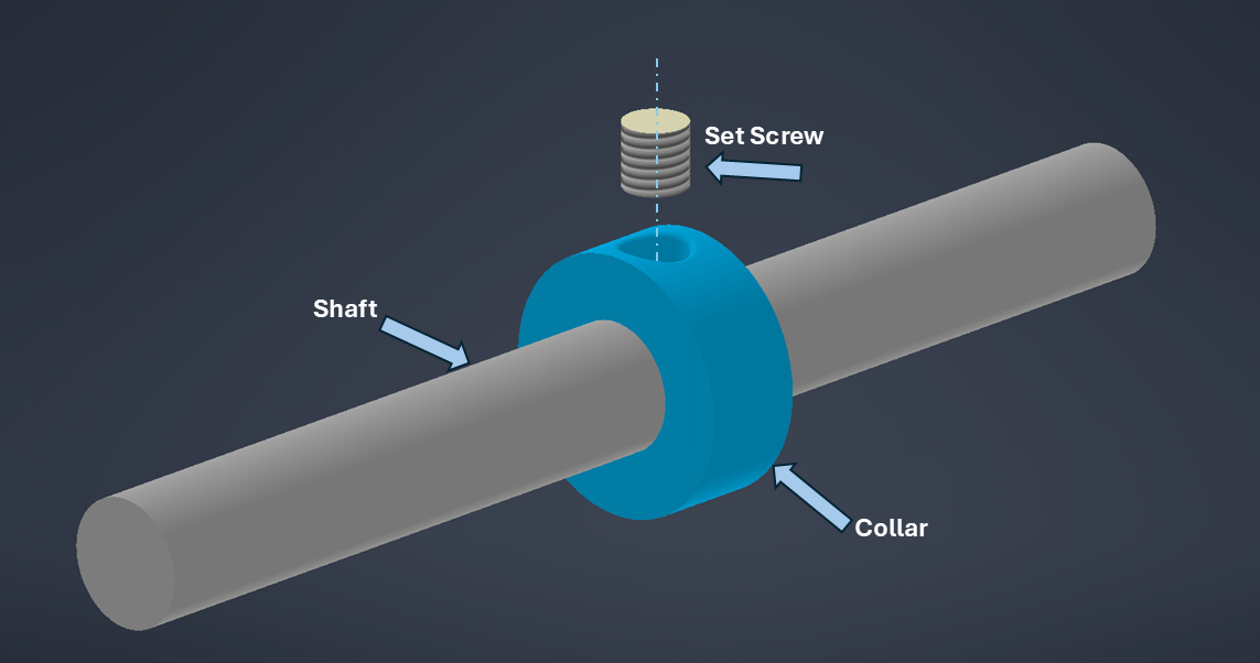
Set Screws: fasten collars, gears, and pulleys to shaft
Self-Tapping Screws: designed to form or cut threads into a hole
Screw Thread Inserts: Internally threaded plugs designed to be inserted into an unthreaded hole. Usually assembled in a weaker material to provide stronger threads.
image of specialty fasteners
Rivets
Rivets are the most widely used permanent fastening method (Airplanes use millions). They are versatile and vibration-resistant. Typically, a pneumatic hammer will deliver a succession of blows to upset the rivet
image
Press Fitting
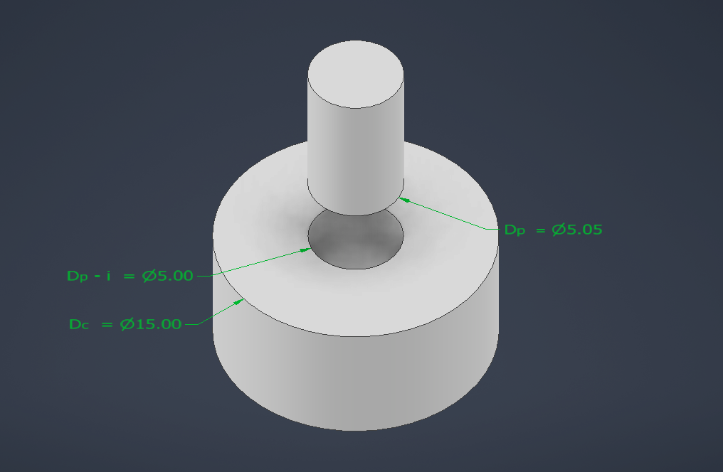
The starting inner diameter of the hole is smaller than the outer diameter of the pin.
Radial or "interference fit" pressure:
where E = Elastic Modulus, i = overlap between ID and OD, \( D_p \) = outer diameter of pin, \( D_c \) = outer diameter of collar
Maximum Joining Stress: (max elastic deformation)
Shrink and Expansion Fits
Joining two parts that have an interference part at room temperature by either heating or cooling one of the parts before coupling.
- Shrink fitting: External part is enlarged by heating, while the internal stays at room temperature
- Expansion fitting: Internal part is contracted by cooling, while the external stays at room temperature
- Diameter change \( \Delta D = \alpha D_0 \Delta T \)
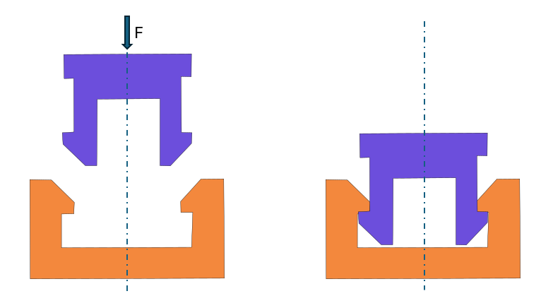
Snap Fits
Mating elements have a temporary interference during assembly, but interlock once assembled. At least one part elastically deforms during assembly, and parts are usually designed for slight interference after assembly.
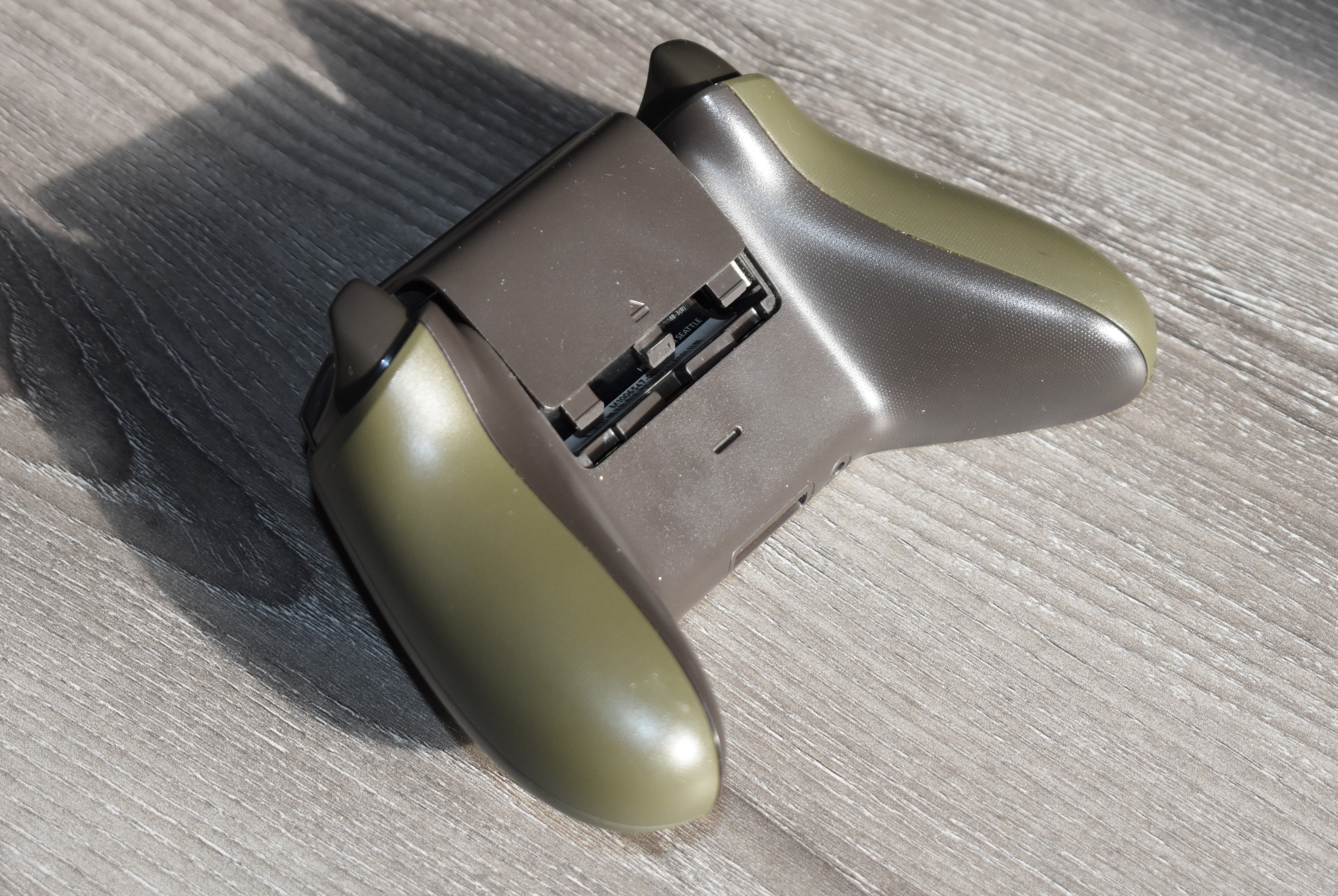
Snap fit example on Xbox Controller
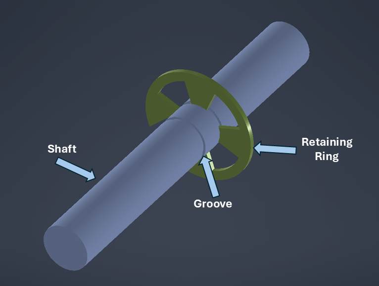
Retaining Ring:
Fastener snaps into a groove along the circumference of a shaft or tube, forming a shoulder. This is used to locate parts or restrict their lateral motion along a rotational shaft.
Integral Fasteners
Components are deformed to interlock with each other as a mechanical joint.
Lanced Tabs: To attach wires or shafts to sheet metal parts
image
Seaming: Edges of metal are bent over to form the fastening seam
image
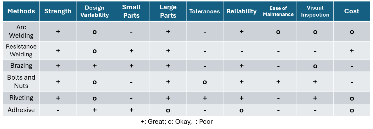
Summary
Content adapted from S. Kalpakjian and S. R. Schmid, Manufacturing Engineering and Technology