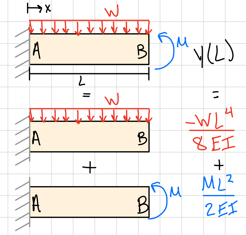
Principle of Superposition
Deformation
Superposition: If the displacements are (1) small and (2) linearly related to the force components acting, the displacements caused by the components can be added up:
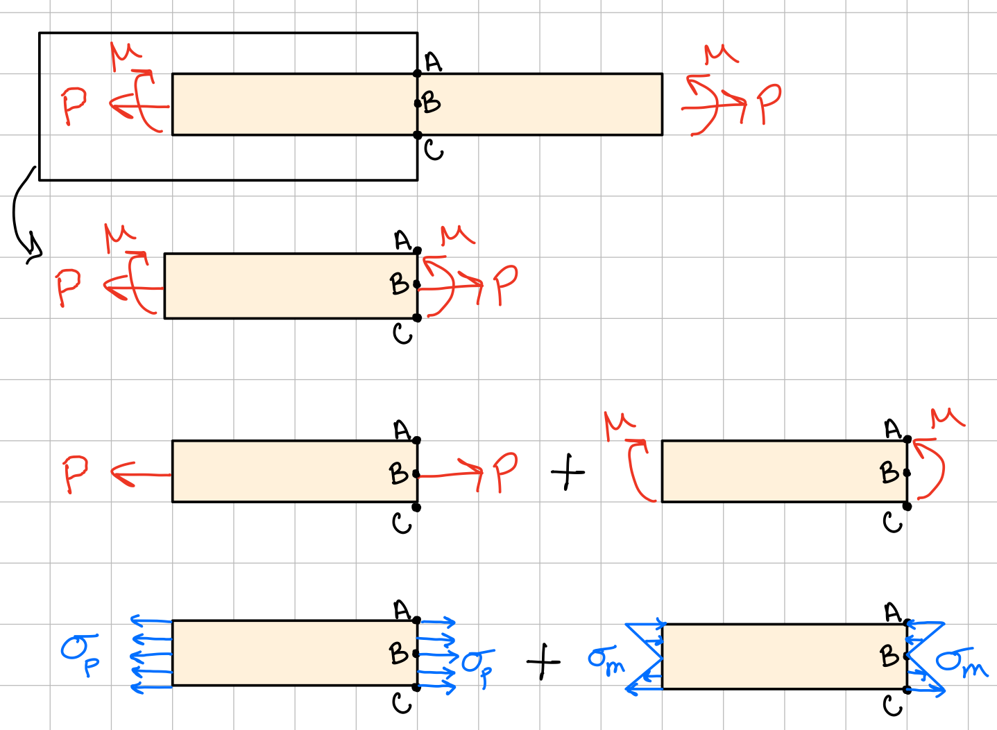
Stress
If a loading results in more than one type of stress, the total stress in a cross-section can be calculated by adding the individual stresses together (superposition). A review of the stresses covered in this course is below:
- Cut the beam to find the find internal forces/moments in a section of interest.
- Calculate all the stresses acting at a specific point within that section.
- Add up like stresses (matching subscripts) to find the total stress state (superposition).
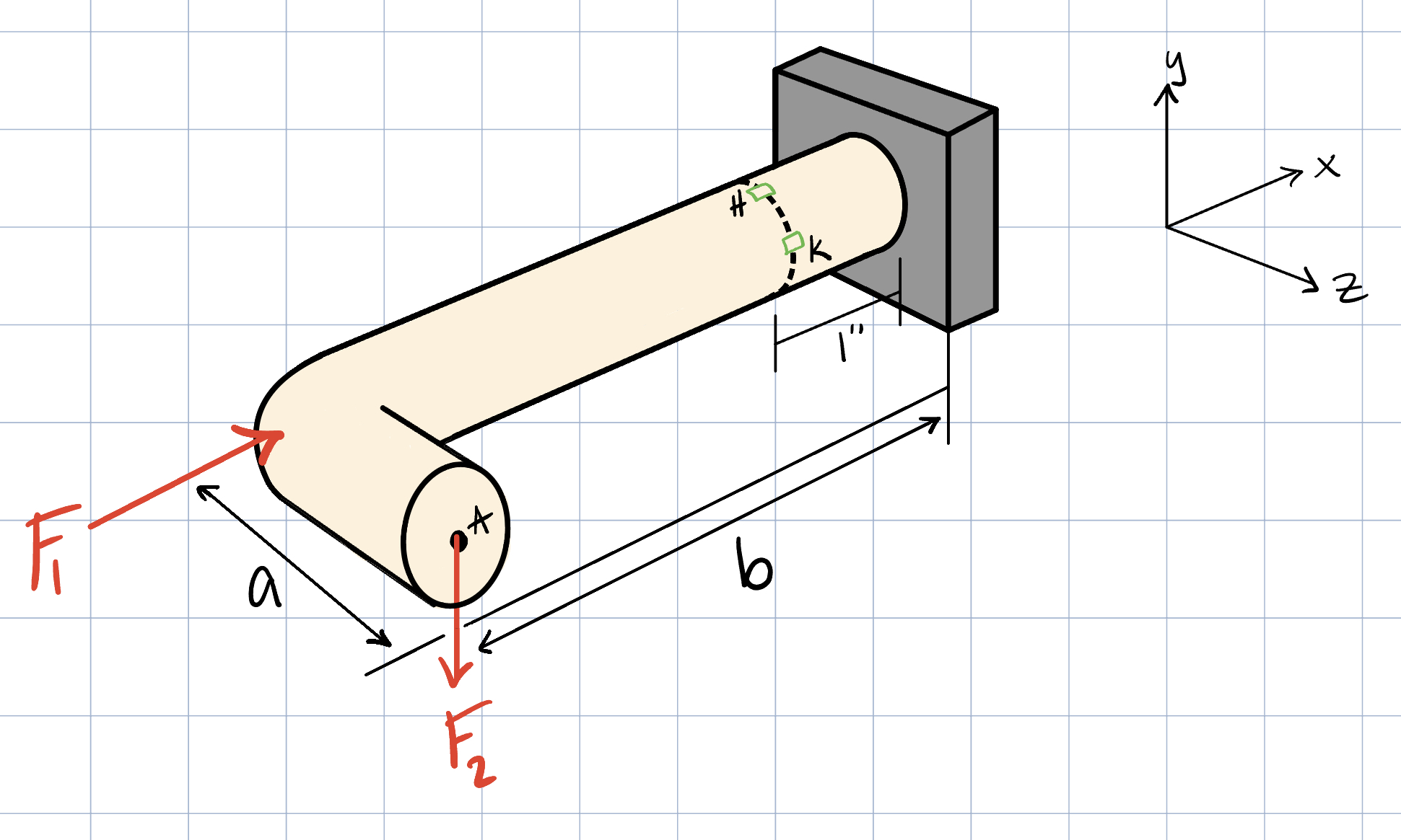
Find the state of stress at points H and K in the given pipe system.
Assume that \( F_1 \) = 2500 lbs, \( F_2 \) = 600 lbs, and the pipe diameter is 1 inch.
Also note that \( a \) = 2.5 inches, and \( b \) = 3.5 inches.
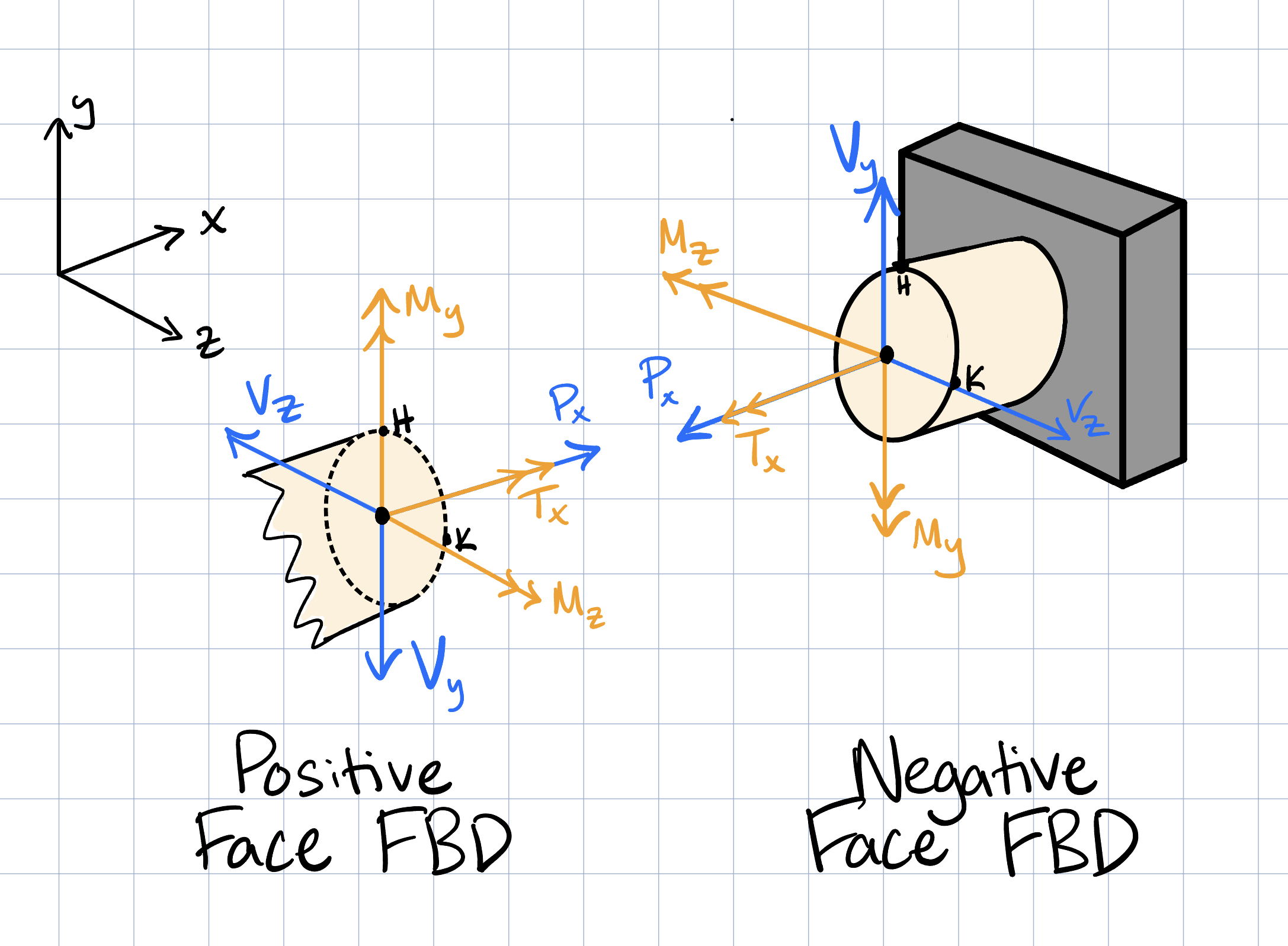
The FBD above depicts all possible forces and moments at the cross section in the positive direction using beam sign convention. Through solving the force and moment balance equations, the magnitudes of some of these forces may turn out to be negative.
First, write all of the six force and moment balance equations.
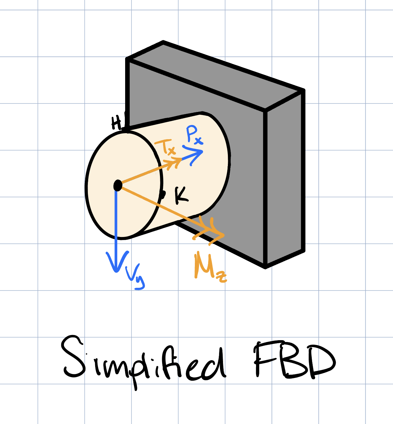
The FBD above shows all forces and moments in their actual direction (with all magnitudes being positive). Note that some of the directions are flipped from the positive sign convention, since we found these forces or moments to be negative.
Next, compute the relevant stresses produced by each force or moment. Note that for this example, \( \sigma_z \) and \( \sigma_y \) would be zero. This is because the normal axis is in the x direction, and there is no internal pressure to create normal stresses in the z or y directions.
For point H:
- Axial: \( \sigma_x = \dfrac{P_x}{A} = \dfrac{F_1}{\dfrac{\pi d^2}{4}} = 3.183 \) ksi
- Shear: \( \tau_{xy} = \dfrac{V_y Q}{It} = 0 \)
- Moment: \( \sigma_x = \dfrac{Mc}{I} = \dfrac{F_2 (b-1) r}{\dfrac{\pi d^4}{64}} = 15.279 \) ksi
- Torsion: \( \tau_{xy} = \dfrac{T_x r}{J} = \dfrac{F_2 a r}{\dfrac{\pi d^4}{32}} = 7.639 \) ksi
For point K:
- Axial: \( \sigma_x = \dfrac{P_x}{A} = \dfrac{F_1}{\dfrac{\pi d^2}{4}} = 3.183 \) ksi
- Shear: \( \tau_{zx} = \dfrac{V_y Q}{It} = \dfrac{F_2\dfrac{2 r^3}{3}}{\left(\dfrac{\pi d^4}{64}\right) d} = 1.019 \) ksi
- Moment: \( \sigma_x = \dfrac{Mc}{I} = 0 \)
- Torsion: \( \tau_{zx} = \dfrac{T_x r}{J} = \dfrac{F_2 a r}{\dfrac{\pi d^4}{32}} = 7.639 \) ksi