Introduction
In general, the study of fluids can be broken down into fluid statics and fluid dynamics. Fluid statics refers to the subset of fluid problems wherein a fluid is at rest or, at least, there is no relative motion between adjacent particles or fluid layers. Under these conditions, shearing stresses are absent and pressure is the dominant and often the only relevant force acting on the surface of a given fluid particle. Analyzing static fluid systems is typically a much simpler task than their dynamic counterparts; however, it remains essential to understand many real-world systems or phenomena.
In studying the static behavior or conditions of a fluid, a major focus is quantifying how pressure varies within a fluid due to external forces, most commonly gravity. This leads to key concepts such as hydrostatic pressure variation, pressure forces on submerged surfaces, and buoyancy among others. These principles form the foundation for applications ranging from hydraulic systems and dams to atmospheric pressure and manometry to the design of ships or floating structures.
Pascal's Law
Again, pressure is a type of normal stress that acts perpendicular to any surface in a fluid, be it real or imaginary. We can define pressure at a point through which the plane under consideration passes through; however, we must understand how the pressure at this point changes with respect to the orientation of the plane passing through it.
By considering a particle of fluid with pressure forces acting at each face with a finite weight, it can be shown that as the dimensions of this particle become small (the volume limits to a point), the pressure forces acting on each face must be equal. This result belies a more general conclusion known as Pascal's Law:
The pressure force acting at a given point in a fluid at rest or in motion but devoid of any shearing forces does not depend on directionThis means that for a static fluid, a single value characterizes the pressure at a point at the corner of a tank, which is in contact with two sides of the tank oriented at different directions. Again, the independence of pressure at a point with respect to direction is only valid if shear stresses are not present.
Pressure Variation Between Points
Next, it is important to understand the variation in pressure within a fluid, that is, to understand how pressure changes from one point to another. Invoking the "Big Idea of Fluid Mechanics" covered in Chapter 1, the dominant forces acting on a static fluid body are typically gravity and pressure forces alone. Again, by considering a particle of fluid affected only by gravity and pressure forces and and completing a force balance, it can be shown that the general equation of motion is given by:
This equation represents a balance of pressure and body forces on a fluid element. Recall that the 'del' or gradient operator is defined as:
and \( \nabla p \) denotes the spatial rate of change (gradient) of pressure. Note that in this general form, this is a vector equation where gravity acts in the \( - \hat{k} \) direction.
For a fluid truly at rest \( \mathbf{a} = 0 \) so that
which implies that
This is the critical relationship that describes the pressure variation in a fluid at rest. Note here that the pressure does in a fluid at rest does not change in directions that are perpendicular to gravity ( in the x-y plane in this case). Instead, the pressure variation within a fluid depends only on its depth, that is, pressure increases as one moves deeper in a fluid and decreases as one moves upward in the resting fluid.
Integrate the governing equation to arrive at an expression for pressure as a function of position in a fluid. Note that the expression \( \rho g \) need not be constant; however gravity can be assumed constant in many cases and density constant for incompressible fluids like water. After integrating we arrive at:
where:
- \( p(z) \) = pressure at elevation \( z \)
- \( p_0 \) = pressure at reference elevation \( z_0 \)
- \( \rho \) = fluid density
- \( g \) = gravitational acceleration
- \( z \) = vertical coordinate (positive upward)
Conceptually, this equation expresses the fact that the pressure in a fluid necessarily increases with depth to support the increasingly heavy column of fluid above it. For a given working fluid, this also means that pressure difference can be conveniently expressed in terms of the height of a fluid column that it could support. The value of the height of this fluid column is then referred to as the pressure head:
It is extremely common to see changes in pressure, even under conditions that are not hydrostatic, expressed as pressure head with length dimensions. Many pump pressure differentials, for instance, are quoted in terms of head. In most cases, the working fluid that defines a given pressure head measurement is water; however any working fluid of known density could be used in principle.
Bottom Line
The main conclusion of this hydrostatic analysis is to show that for a fluid at rest, the pressure distribution is a sole function of the vertical coordinate with respect to gravity. This can produce results that initially may seem intuitive, such as the fact that the pressure at same depths of differently shaped containers with identical fluids are the same as shown below.
Pressure References
When accounting for a generic pressure measurement, a few different reference levels are common:
- Absolute pressure (\( p_{\text{abs}} \)): measured relative to a perfect vacuum (zero pressure).
- Gage pressure (\( p_{\text{gage}} \)): measured relative to the local atmospheric pressure.
The relationship between them is:
Gage pressure is most commonly used in engineering applications since many instruments read pressure relative to atmospheric conditions. Absolute pressure is required when vacuum conditions or thermodynamic relations are involved. Note that in many cases, pressure differentials, as opposed to single pressure values, are what affect system performance, in which case either reference system can be used in calculations.
Manometry
Manometers are a class of devices that leverage the principles of hydrostatics to measure pressure, inferring it from the height of a column of a fluid. There are various types of manometers of varying degrees of complexity and precision; however, they all follow the same general principle. By expressing an unknown pressure in terms of a known reference pressure and the height of a working fluid column, an unknown pressure or a pressure differential can be accurately quantified.
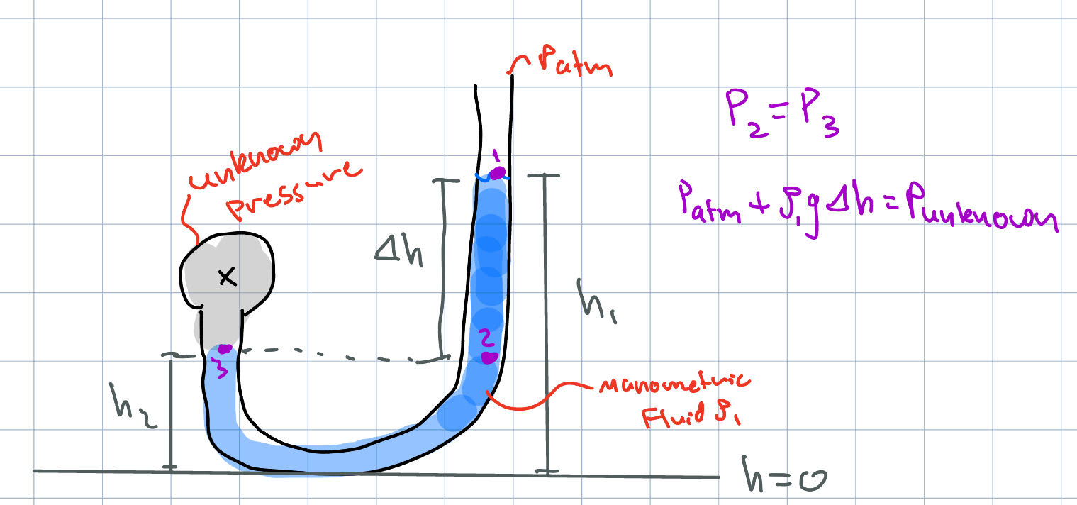
Simple U-Tube Manometer
For a manometer with a single working fluid:
where \( \Delta h \) is the vertical height difference between the two columns.
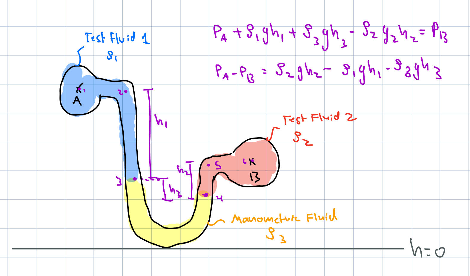
Differential Manometer (Multiple Fluids)
When multiple fluids are present, sum contributions from each segment:
Each term corresponds to a fluid column with density \( \rho_i \) and height change \( \Delta h_i \).
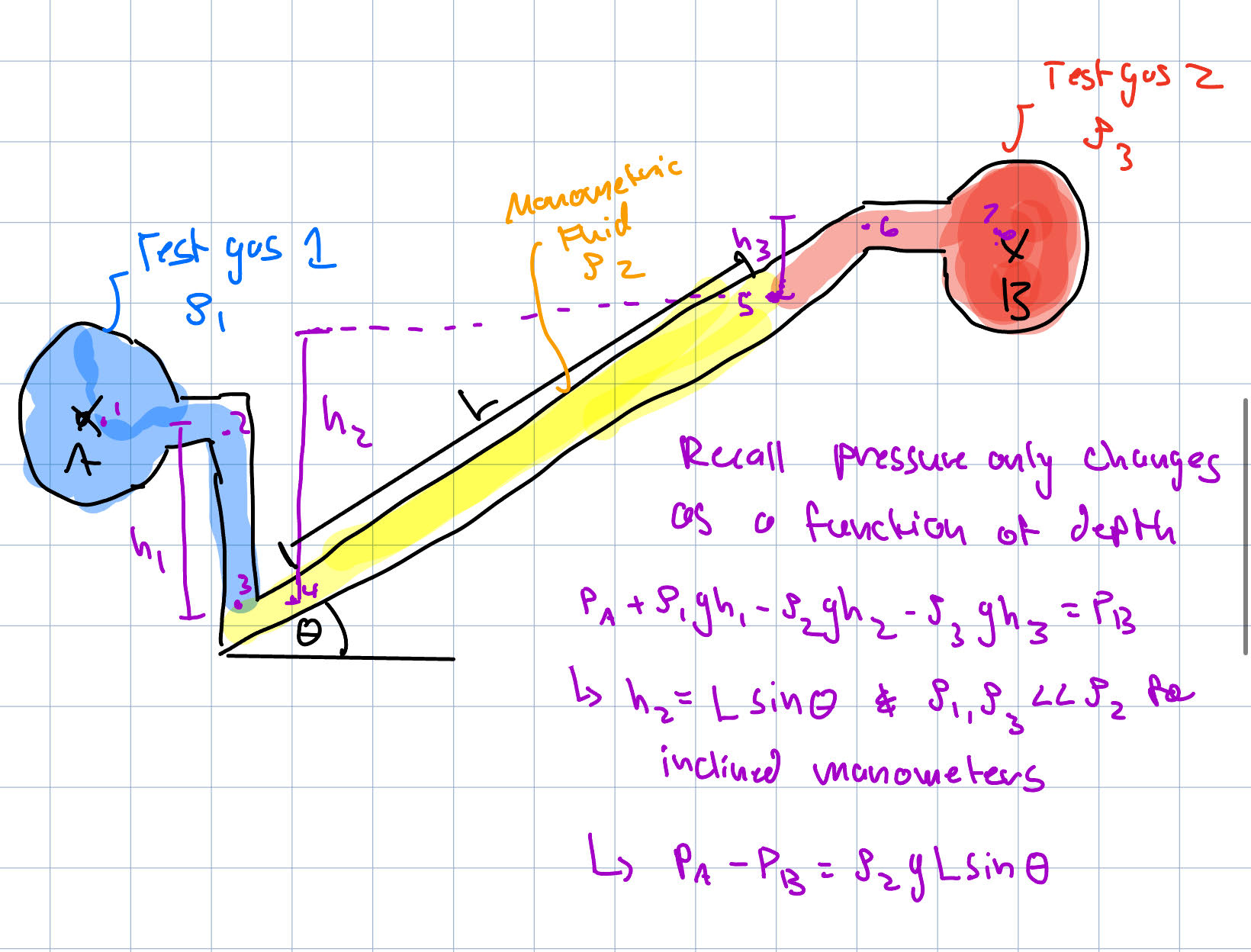
Inclined Manometer
For improved sensitivity an inclined manometer can be used. For inclined manometers, small pressure differences can translate to sizable changes in the length \( L \) of a working fluid which improves the resolution of the device. Inclined manometers are frequently used to compare pressure differences between gases. Under these conditions, if the manometric fluid is a liquid, it is often reasonable to neglect the hydrostatic effects of the gas and use only the manometric fluid level as a proxy for pressure difference.
where \( L \) is the length along the incline and \( \theta \) is the angle.
Recall
- Only vertical height differences matter (not path shape)
- Always track signs carefully when moving up/down
- Use consistent datum/reference level
- Pressure at the same horizontal level in the same fluid is equal
General Relation for Manometry
For any connected static fluid system, pressure changes can be found by moving vertically through the fluid:
- Moving downward in a fluid: add \( +\rho g \Delta h \)
- Moving upward in a fluid: subtract \( -\rho g \Delta h \)
- Pressure is continuous across interfaces
Hydrostatic Forces
An important component of hydrostatics is computing the forces and locations of forces acting on surfaces that are submerged in a fluid. Intuitively, these forces will depend on the nature of the fluid, namely its density, the depth that the surface is submerged and the overall shape of the surface. In general, it is useful to calculate the magnitude and orientation of the resultant force acting on a submerged surface and the center of pressure, that is, the point through which the resultant force acts.
Planar Surfaces
A planar surface is a flat, two-dimensional surface with no curvature. In fluid statics, pressure acts normal to the surface and varies with depth, but the surface itself lies entirely in a single plane.
Resultant Force
The total hydrostatic force on a plane surface is:
For a plane surface in an incompressible fluid:
where:
- \( A \) = area of the surface
- \( h_c \) = vertical depth of the centroid below the free surface
- \( \rho \) = fluid density
- \( g \) = gravitational acceleration
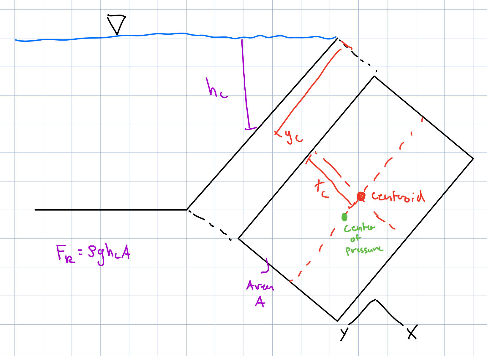
Center of Pressure
The line of action of the resultant force acts at the center of pressure. The location of the center of pressure on the planar surface of interest can be found with the following equations:
where:
- \( y_p \) = depth of center of pressure
- \( I_{xc} \) = second moment of area about the centroidal axis (parallel to free surface)
where \( x_p \) is the horizontal coordinate of the center of pressure, \( x_c, y_c \) are centroid coordinates, \( A \) is the area, and \( I_{xy,c} \) is the product of inertia about centroidal axes.
Critically, see how the center of pressure is always below or deeper than the centroid of the planar surface since \( \frac{I_{xc}}{y_c A} \) is always positive. With increasing depth, however, this difference becomes smaller. Bear in mind also that the product of the inertia, \( I_{xy,c} \), will be zero if the submerged surface is symmetric about any axis passing through its centroid that is parallel to the x or y axes. This means that for symmetric shapes, the center of pressure will have an x-coordinate that coincides with the centroid.
In general, when performing hydrostatic analysis on planar surfaces it is helpful to keep the following in mind:
- Resultant force equals pressure at centroid times area
- Force always acts normal to the surface
- Center of pressure is always below the centroid
- Depth must be measured vertically
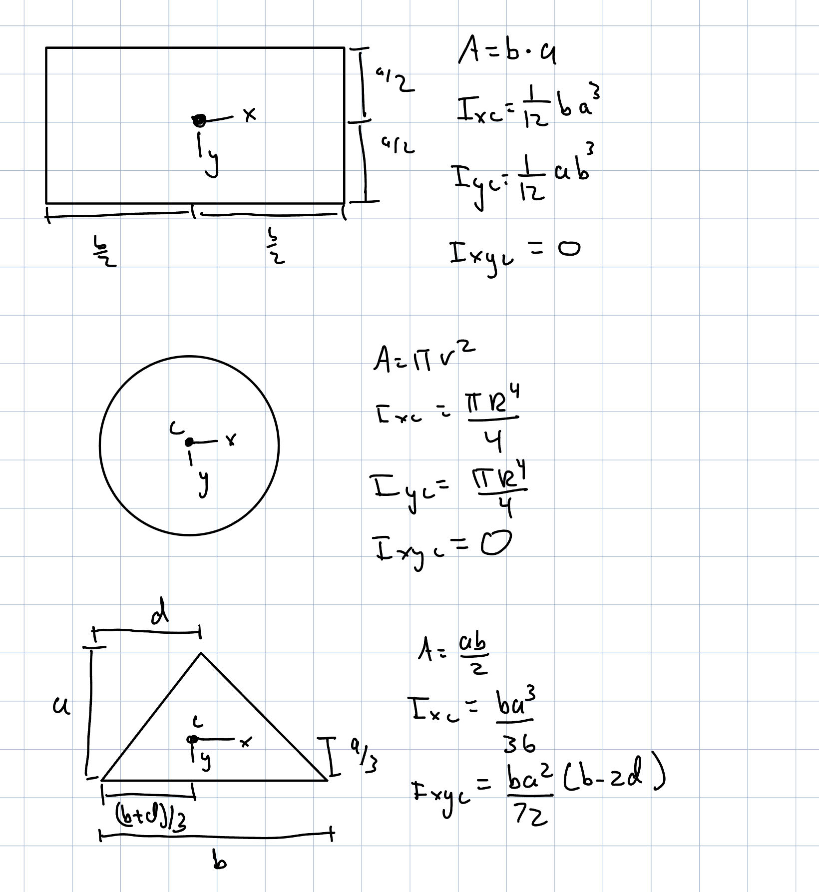
The following is a short visual of second moments of area with respect to coordinate axes and templates for finding the centroids of common planar shapes.
Curved Surfaces
For curved surfaces, pressure forces act normal to the surface and vary with depth. Instead of integrating directly, which for curved surfaces can be especially cumbersome, the resultant force of the fluid on the surface can be found by conducting an equilibrium analysis on the fluid in contact with the curved surface itself.
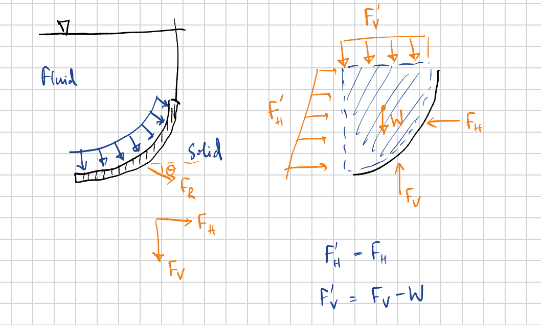
Horizontal Component
The horizontal force equals the hydrostatic force on the vertical projection of the surface:
where:
- \( A_v \) = vertical projected area
- \( h_c \) = depth of centroid of the projected area
The line of action passes through the center of pressure of the projected area.
Vertical Component
The vertical force equals the sum of weight of the fluid in this control volume and the pressure force acting in the vertical direction on the control volume:
where:
- \( V \) = volume of fluid directly above the curved surface
Direction:
- Upward if fluid is below the surface
- Downward if fluid is above the surface
Resultant Force
Recall that in this equilibrium analysis, the water volume was considered so that the reaction force acted upon the water. The resultant force of the water on the curved surface, therefore, will be equal in magnitude but opposite in sense. The total force is found from components:
and acts at an angle:
This derivation for a curved surface is not general. Expressions may differ for surfaces of different shapes or orientations; however, applying Newton's 2nd Law allows the resultant force to be calculated, so long as pressure forces acting on a control volume of water can be calculated. For curved surfaces it is helpful to keep in mind:
- Break curved surface problems into horizontal and vertical components
- Horizontal force acts on projected area
- Vertical force equals weight of fluid above
- Resultant force found via vector addition
Buoyancy
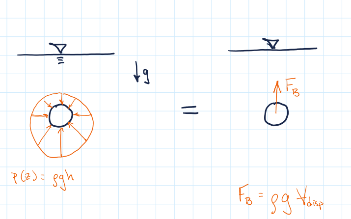
Buoyancy refers to the net force experienced by an object that is submerged or partially submerged in a fluid due to that fluid. It arises due to variation of pressure with depth a fluid. Since pressure increases with depth, a submerged body experiences a net upward force.
Buoyant Force
The buoyant force is equal to the weight of the fluid displaced by the body:
where:
- \( F_B \) = buoyant force
- \( \rho_f \) = fluid density
- \( V_{\text{disp}} \) = volume of fluid displaced
This is known as Archimedes' Principle.
Note that the relevant volume for Archimedes' Principle is the volume of displaced fluid. This explains how objects one might expect to sink actually float like a concrete canoe or a large steel battleship. These objects displace an amount of fluid that weighs more than they do; they are hollowed out to achieve this. It's also useful to think of buoyancy in terms of average density; the average density of a ship due to its mostly air-filled interior, is smaller than that of water, so it floats.
Line of Action (Center of Buoyancy)
The buoyant force acts through the center of buoyancy, which is the centroid of the displaced fluid volume.
Floating vs Submerged Bodies
Fully submerged:- \( V_{\text{disp}} = V_{\text{body}} \)
- Buoyant force depends only on fluid properties and body volume
- Body adjusts until forces balance:
- Only a portion of the body is submerged
- Displaced volume determined by weight: