Additive Manufacturing
Additive Manufacturing (AM) is a process that builds parts layer-by-layer directly from a digital model, rather than subtracting from a bulk material like conventional manufacturing processes. Additive manufacturing enables complex geometry, lightweighting, and part consolidation. 3D Printing is one category of additive manufacturing.
3D Printing Process
- 1. 3D CAD model is converted to STL (Standard Tessellation Language)
- 2. Model is sliced into 2D layers
- 3. Each layer is fabricated sequentially
- 4. Support material may be required, depending on geometry and process.
Callout
Standard Tessellation Language (STL) represents surfaces using triangular facets
Tessellation: surface represented by triangles
image
Advantages and Disadvantages
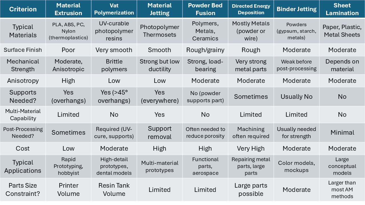
There are a wide range of 3D Printing technologies that each have their own unique properties. Between them, you can optimize certain qualities with other tradeoffs, but these refer to 3D Printing as a whole.
Advantages- Easy and quick to change part design and produce a new version (rapid prototyping)
- Limited skills or training needed to make parts
- Reduced individual manufacturing time with no prep time required
- Cost of production unique parts in small quantities is relatively low
- Some parts can be made pre-assembled
- Part tolerances/surface finish:
- Staircase Effect on sloped surfaces from slicing and layer thickness
- Shrinkage or distortion of manufactured parts from uneven cooling
- Holes come out smaller and posts bigger than CAD dimensions
- Limited variety of possible materials
- Post-processing of parts may be required
- Cost and time does not improve with increased volume
- Part size is generally limited
- Porosity and mechanical property challenges
- Material anisotropy, i.e. mechanical properties within layers vary from those between layers
Types of 3D Printing Processes
- Material Extrusion (MEX)
- Fused Deposition Modeling (\( (FDM)^{TM} \))
- Fused Filament Fabrication (FFF)
- Vat Polymerization (VAT)
- Stereolithography (SLA)
- Digital Light Processing (DLP)
- Continuous Digital Light Processing (CLIP)
- Liquid Crystal Display (LCD)
- Material Jetting
- Poly Jet
- Nanoparticle Jetting
- Drop on Demand (DOD)
- Directed Energy Deposition (DED)
- Laser Engineered Net Shaping (\( LENS^{TM} \))
- Electron Beam Additive Manufacturing (EBAM)
- Wire Arc Additive Manufacturing (WAAM)
- Friction Stir Additive Manufacturing (FSAM)
- Powder Bed Fusion (PBF)
- Selective Laser Sintering (SLS)
- Selective Laser Melting (SLM)
- Direct Metal Laser Sintering (DMLS)
- Electron Beam Melting (EBM)
- Selective Heat Sintering (SHS)
- High-Speed Sintering
- Multi-Jet Fusion (MJF)
- Binder Jetting
- Sheet Lamination
- Laminate Object Manufacturing (LOM)
- Selective Lamination Composite Object Manufacturing
- Plastic Sheet Lamination
- Selective Deposition Lamination
- Composite Based Additive Manufacturing
- Ultrasonic Consolidation
- Ultrasonic Additive Manufacturing (UAM)
Material Extrusion (MEX)
This is what most people picture when they think of 3D Printing
Also known as: Fused Deposition Modeling (FDM), Fused Filament Fabrication (FFF)
- Heated thermoplastic filament extruded through a nozzle, layers fusing together in cooler air
- Machine deposits layers by moving nozzle horizontally, tracing 2D cross sections, then moving vertically and repeating
- 3+ DOF machines exist for non-planar slices, but much more complex and less common
- Support structure needed for steeply overhanging parts
- Main Materials: PLA, ABS, PC, Nylon
- Typical layer thickness: \( 0.1 \)–\( 0.3 \) mm
- Surface finish is generally not as good as other methods
MEX Numerical Example
Given:- Nozzle diameter \( d = 0.4 \) mm
- Layer height \( h = 0.25 \) mm
- Extrusion speed \( v = 50 \) mm/s
- Delay between layers = 5 s
- Part: \( 30 \times 30 \times 30 \) mm cube
- Solid Cube
- 25% Infill
Solution:
Volumetric flow rate:
Number of layers:
Total inactive time:
(1.) Solid Cube
Volume:
Time to extrude:
Total production time:
(2.) 25% Infill
Interior dimensions:
Interior volume:
Material used:
Extrusion time:
Total production time:
Traverse Path Method (Check)
Tracks per layer:
Travel distance per layer:
Time per layer:
Total extrusion time:
Total production time:
Vat Polymerization (VAT)
- UltraViolet laser cures UV-curable polymer (or resin) dissolved in a solvent- Liquid Deposition Process
- Laser may be positioned above or below resin tank (top-down vs bottom-up)
- Support structures required when overhang angle exceeds \( 45^\circ \), since cured resin is denser than uncured
- SLA, DLP, CLIP are common variants
- Typical layer thickness: \( 0.025 \)–\( 0.1 \) mm
VAT Numerical Example
A rectangular part with dimensions \( 20 \text{ mm} \times 10 \text{ mm} \times 10 \text{ mm} \) is fabricated using a vat photopolymerization process.
Given:
- Layer thickness \( t = 0.2 \) mm
- Part height \( H = 10 \) mm
- Laser scanning speed \( v = 1000 \) mm/s
- Laser spot diameter \( D = 0.2 \) mm
- Delay per layer (stage movement in \( z \)-direction) \( t_d = 10 \) s
- Cross-sectional area per layer \( A = 200 \) mm\( ^2 \)
- Number of layers
- Time to write one layer (including delay)
- Total fabrication time
- Volumetric method approximation for fabrication time
Solution:
- Number of layers:
- Time to write one layer:
- Total fabrication time:
- Volumetric method:
Total part volume:
Volumetric build rate:
Total time:
Material Jetting
- Individual droplets of photopolymer deposited layer-by-layer and UV-cured
- Machines typically have 2 sets of print heads, one for main material and one for support, with multiple nozzles on each head
- Uses viscous thermosetting resin that is cured by high intensity UV, with a secondary support material that is water-soluble.
- Multiple materials and colors possible
- Typical layer thickness ~0.02 mm
Powder Bed Fusion (PBF)
- Laser or electron beam selectively melts heat-fusible powder (thermoplastics, metals, or ceramics)
- After each layer, a new layer of loose powder is spread across the surface
- Unfused powder acts as support structure for overhanging parts, but powder in a 10 mm thick shell around the part is thermally damaged
- Undamaged powder can be poured out of complete part to be reused
- Typical layer thickness: \( 50 \)–\( 100\ \mu \)m
Directed Energy Deposition (DED)
- The material (usually a metal powder) and the energy for fusion (usually laser heating) are simultaneously focused at the same location
- The metal powder is projected onto a surface where the laser directly melts the powder in place
- Can be combined with in-situ machining, combining both machining and deposition in a single machine
- Suitable for repair and large structures
- Tool change or part shifting required, requires specialized toolpath planning
Binder Jetting
- Liquid adhesive is selectively deposited to join powder materials (metals, gypsum, or starch), which are deposited in thin layers
- Parts are weak before post-processing
Laminated Object Manufacturing
- The input is a roll of thin sheet material (paper, plastic, or metal) coated with an adhesive
- Successive layers are cut by a laser in the required shape and stacked to build up the part
Design Guidance for AM
- 1. Minimize unnecessary material
- 2. Choose a print orientation that is aware of the direction of anisotropy, mechanical properties, surface finish, roundness of holes, support materials, etc.
- 3. Reduce support structures
- 4. Iterate steps 1-3
Design Advisor