Buckling Introduction
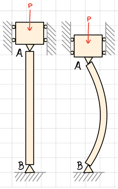
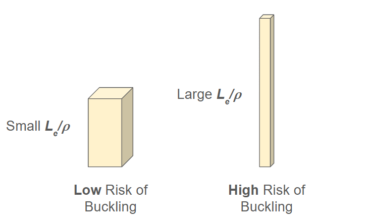
Buckling failure occurs in slender beams under compressive loads. With large enough loads, these beams begin to bend with even slight disturbances. Once this happens, the original load induces further bending, leading the beams to yield at a significantly lower force than they would under pure compression. This document covers the relationship between beam dimensions and susceptibility to buckling, and it specifies the criteria to avoid buckling.
Buckling Criteria
Critical Load:
To figure out the minimum compressive load \( P \) needed for buckling risk, we need the linear beam deflection equation:
We can find the value of \( M(x) \) by isolating a section of the beam and drawing a free body diagram:
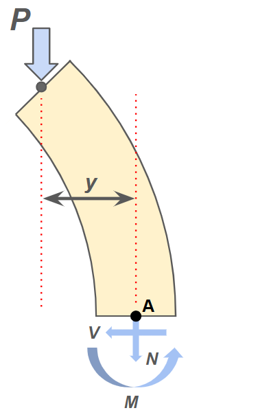
Here it can be seen that the internal bending moment counteracts the force couple \( Py \). We then insert the condition \( M=-Py \) into the deflection equation, obtaining the following:
This ODE has general solution
and the constants \( A \) and \( B \) can be identified by applying boundary conditions.
For example, let's say the beam has pinned connections on both ends. The beam deflection at the ends must then equal 0. At the top end, the equation is
Similarly, at the bottom end, the equation is
\( A \) is not explicitly 0, so the sine function itself must equal 0:
For this to be true, the argument of the sine must be a multiple of \( \pi \). Thus,
We are concerned with the smallest load where buckling will occur, so we take \( n=1) \). Different boundary conditions give slightly different results, but they can all take the form
where \( L_e \) is called the effective length. This result is the Euler model for critical loading.
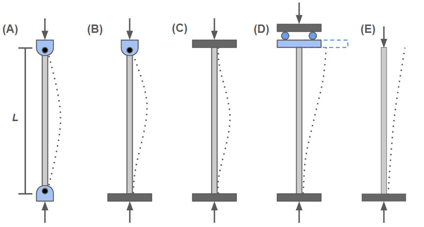
| Condition | A | B | C | D | E |
|---|---|---|---|---|---|
| \( L_e \) | \( L \) | \( 0.707L \) | \( 0.5L \) | \( L \) | \( 2L \) |
Euler Stress Criteria:
We now extend the result from the Euler model to find critical stress:
This result is typically written in a different way. First, we introduce a parameter called radius of gyration:
The critical stress of the beam can then be written as
The fraction \( \frac{L_e}{\rho} \) is called the slenderness ratio. It is directly related to a beam's susceptibility to buckling.
For a given material, critical stress can be plotted as a function of slenderness ratio. These plots are called column design curves, and points above the curve indicate failure. Under the Euler model, a column design curve looks like this:
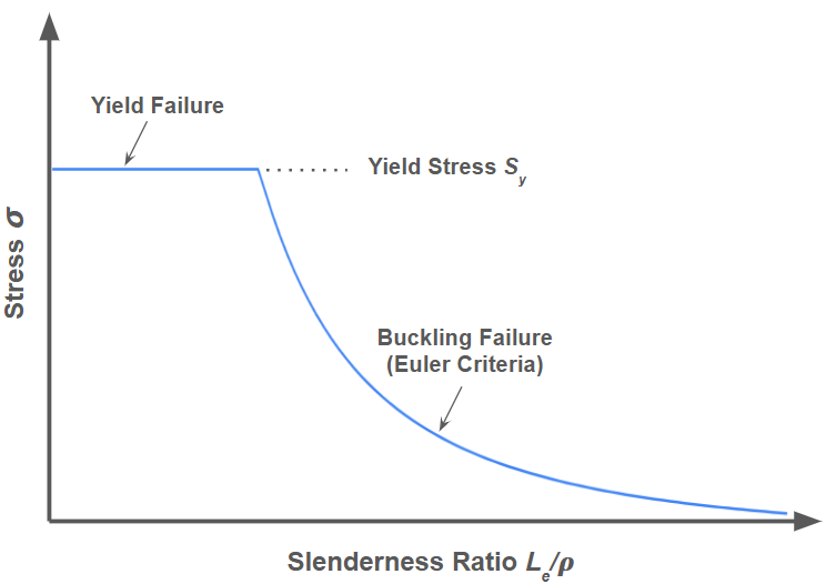
Notice that for low slenderness ratios, the curve becomes a flat line at the yield stress value. This is because the material is predicted to fail under yield before buckling at these points.
Johnson Stress Criteria:
Empirical evidence indicates that Euler's approach is not accurate at small to moderate slenderness ratios. This is due to complex factors involved in real-world loading conditions.
A new empirical model, named the Johnson Criteria, aligns more closely with the observed failure patterns. The model follows this equation:
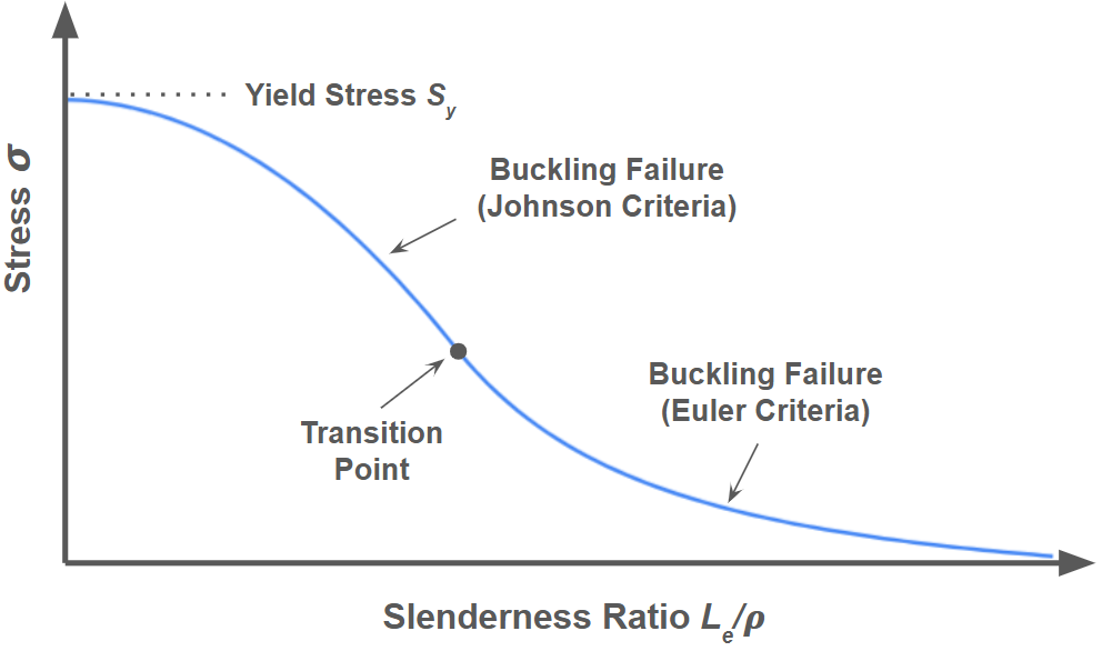
The most accurate column design curves include a combination of Euler and Johnson curves. The transition point between the curves is at the slenderness ratio
The Johnson Criteria is used for slenderness ratios smaller than the transition point, while the Euler Criteria is used for larger ratios. A design curve considering both criteria looks like this: