Planar Mechanisms
Mechanisms are devices that transform motions to some desirable pattern. From door hinges to the gears and levers found in a watch, mechanisms are very important. We will focus on planar (2-dimensional) mechanisms to better understand the design and analyses that go into each mechanism.
Links and Joints
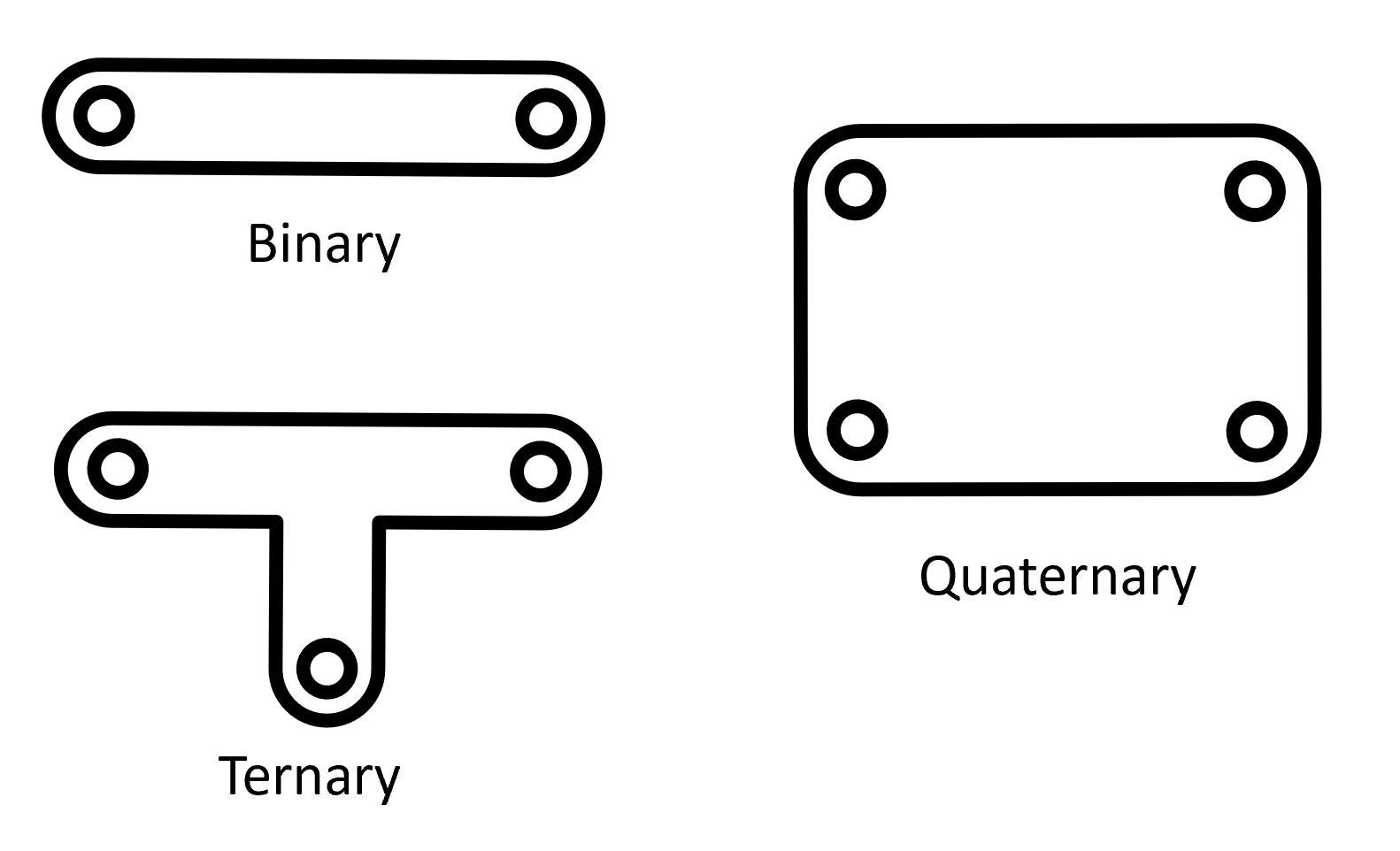
Links are the rigid parts that make up a mechanism. They can have 2 nodes (binary), 3 nodes (ternary), and on and on up to a large amount of other possible points of attachment to other links. Joints are where links connect or contact other objects. There are pin, slider, rolling, and rolling with sliding joints, just to name a few.
DOF
The number of degrees of freedom (DOF) that a linkage or mechanism has is defined by the number of independent coordinates required to define the position and orientation of an object. If you look at a linkage in a 2D space, you can define two translational degrees of freedom, in the x- and y-directions, as well as one rotational degree of freedom to define the angle of the linkage. In 3-dimensions, a linkage has 6 degrees of freedom with three being translational and the other three being rotational. Again, for this section, we will only be focusing on 2D mechanisms.
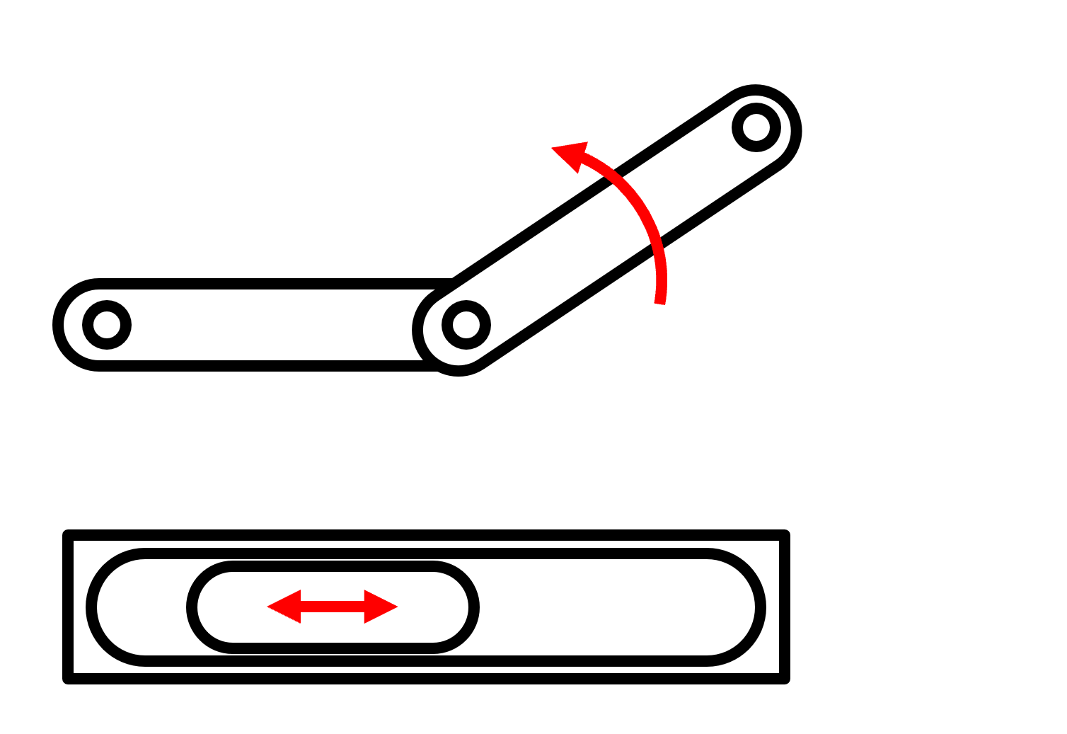
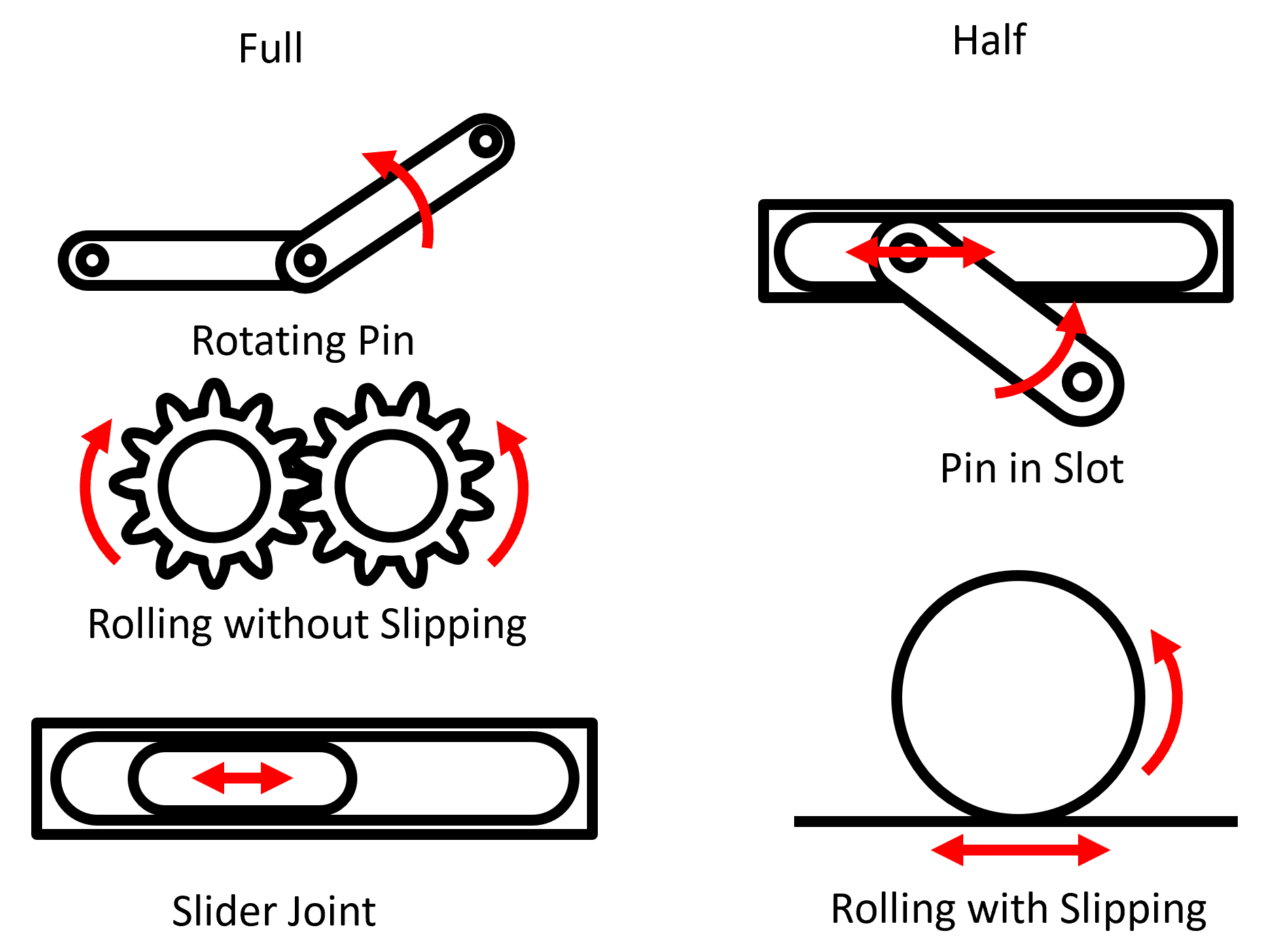
When connecting links, the number of degrees of freedom changes based on the type of joint that connects the two linkages. A full joint only adds one degree of freedom, while a half joint allows for two additional degrees of freedom. An example of a full joint is a pin joint where the added linkage only adds one rotational degree of freedom to the mechanism. A sliding joint is an example of a half joint, which adds a translational and a rotational degree of freedom to be added to the mechanism. On the other hand, when a link is grounded, it has zero degrees of freedom as it is constrained from moving at all.
Gruebler's Equation takes this information and allows us to compute the number of degrees of freedom of a mechanism. It takes the number of links (\( n \)), the number of full joints (\( J_1 \)), and the number of half joints (\( J_2 \)) and is able to determine the mobility of a mechanism.
Gruebler's Equation:
The number of links is subtracted by one to account for the ground link in every mechanism. It subtracts twice the number of full joints because a full joint takes two degrees of freedom. Finally, the number of half-joints is subtracted because each half-joint removes only one degree of freedom in a planar mechanism.
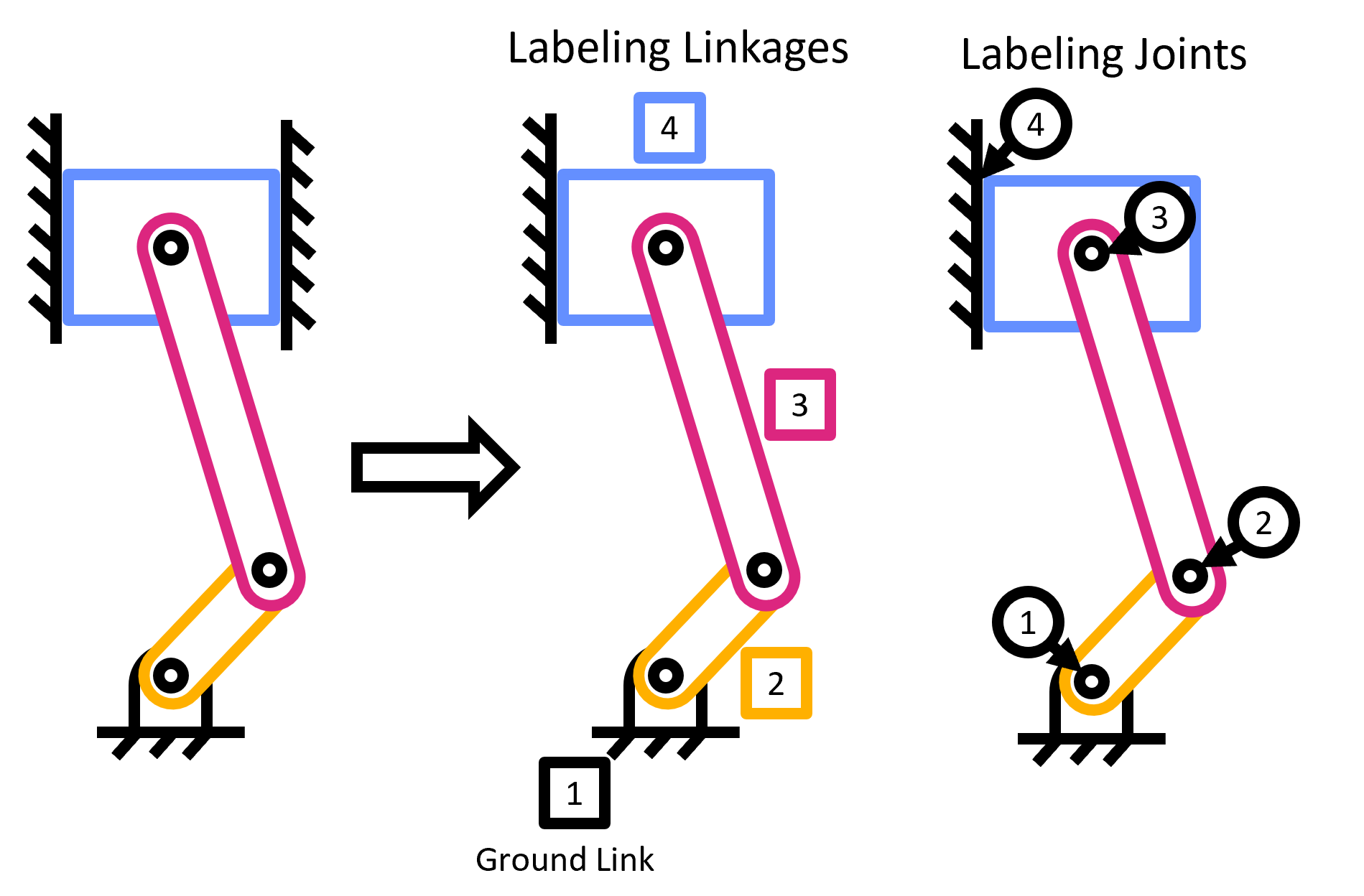
To keep track of each of what is a linkage, a full joint, and a half joint, we use shapes and numbers. In general, when numbering links, use a square around each number. When labeling full joints, circle each number. Lastly, for half joints, put a diamond around each number.
Caution: Grubeler's equation does not always work as it does not account for the size of links, when things are symmetric, or for certain cases of motion. Take a look at these two gears:
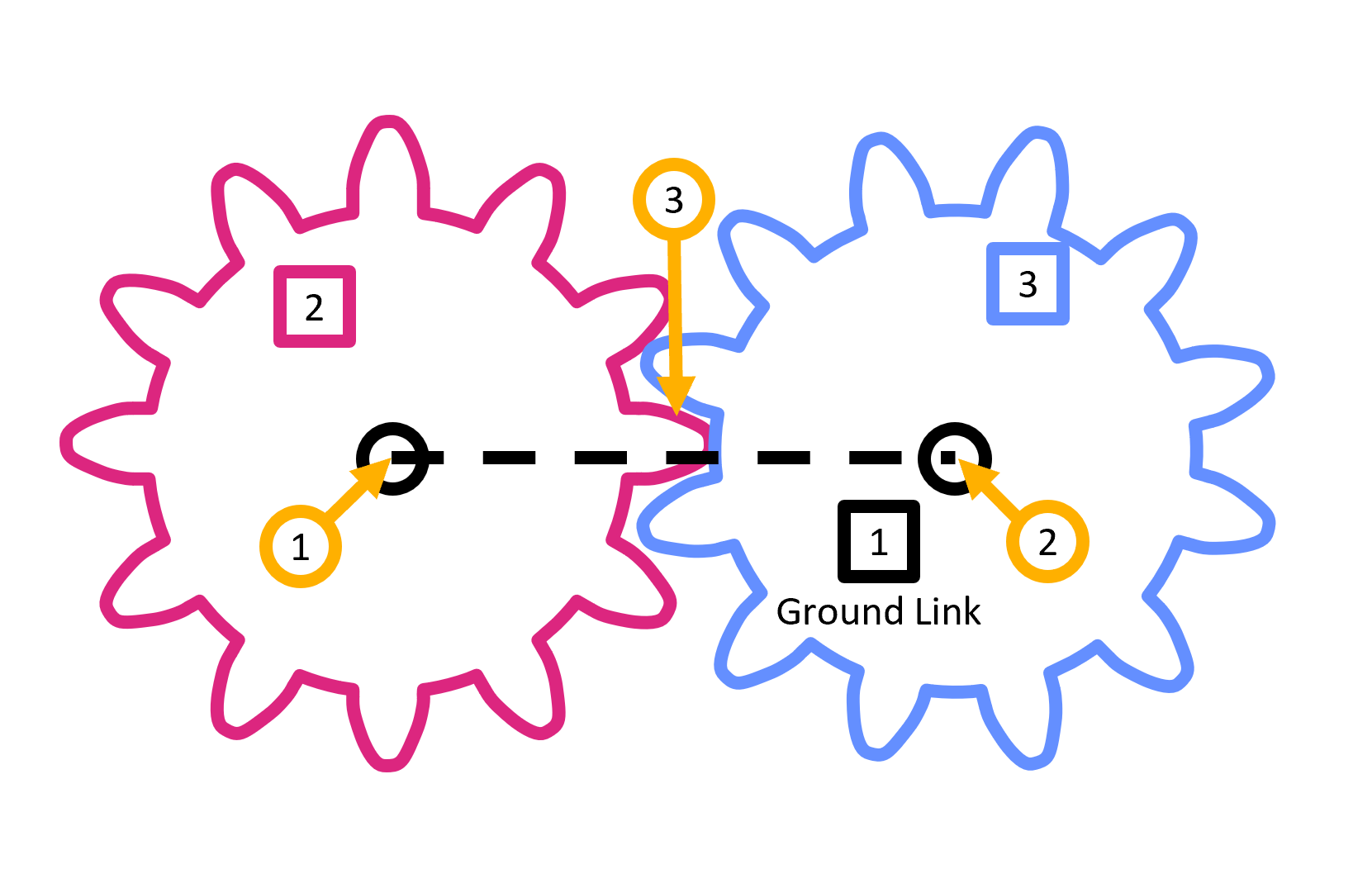
The two gears make up a three bar linkage (the ground plus the two gears). The joint between the two gears is a full joint as it restricts 2 degrees of freedom. By Gruebler's equation:
This predicts no motion of the gears despite the fact that in reality there is one degree of freedom in this mechanism.
Transformation rules
How does the DOF change when we:
- Replace a pin joint with a sliding joint. This is going from one roational degree of freedom to one translational degree of freedom This means that there is no change in DOF for this mechanism.
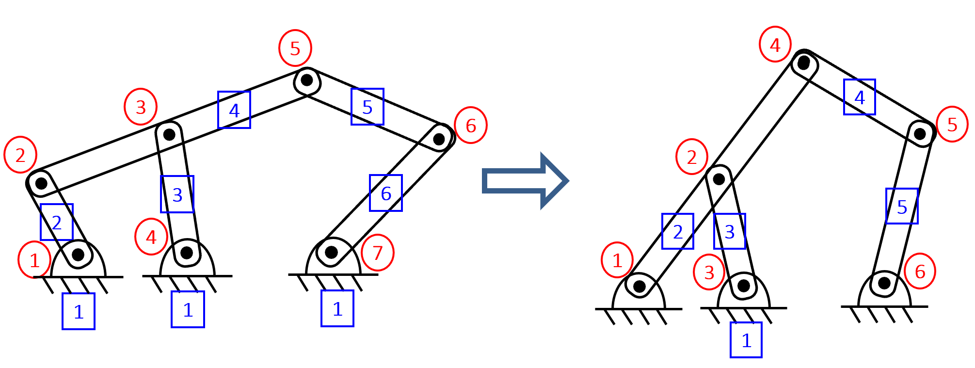
- Remove link and full joint. In this case, the number of links and the number of full joints decreases by one each. Joints add three DOF while full joints remove two degrees of freedom. By removing both of these, the DOF of the linkage decreases by one.
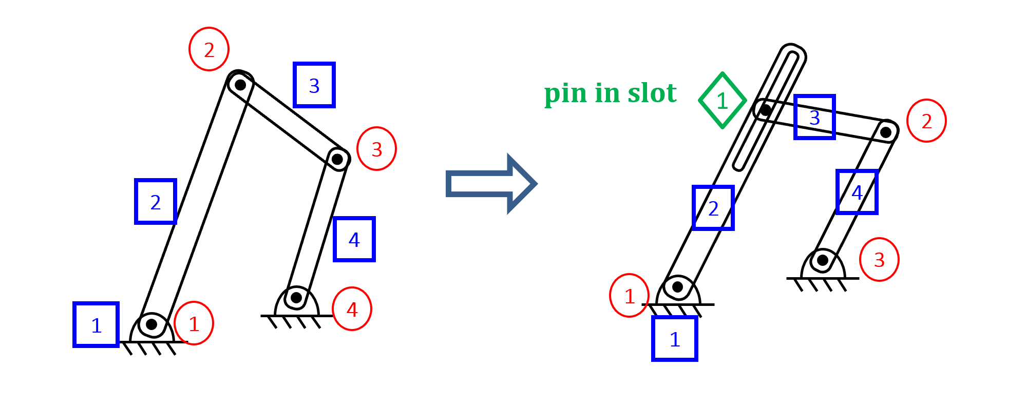
- Change full joint to half joint. A full joint removes two DOF while a half joint only removes one. Going from a full to a half joint makes the DOF increase by one.
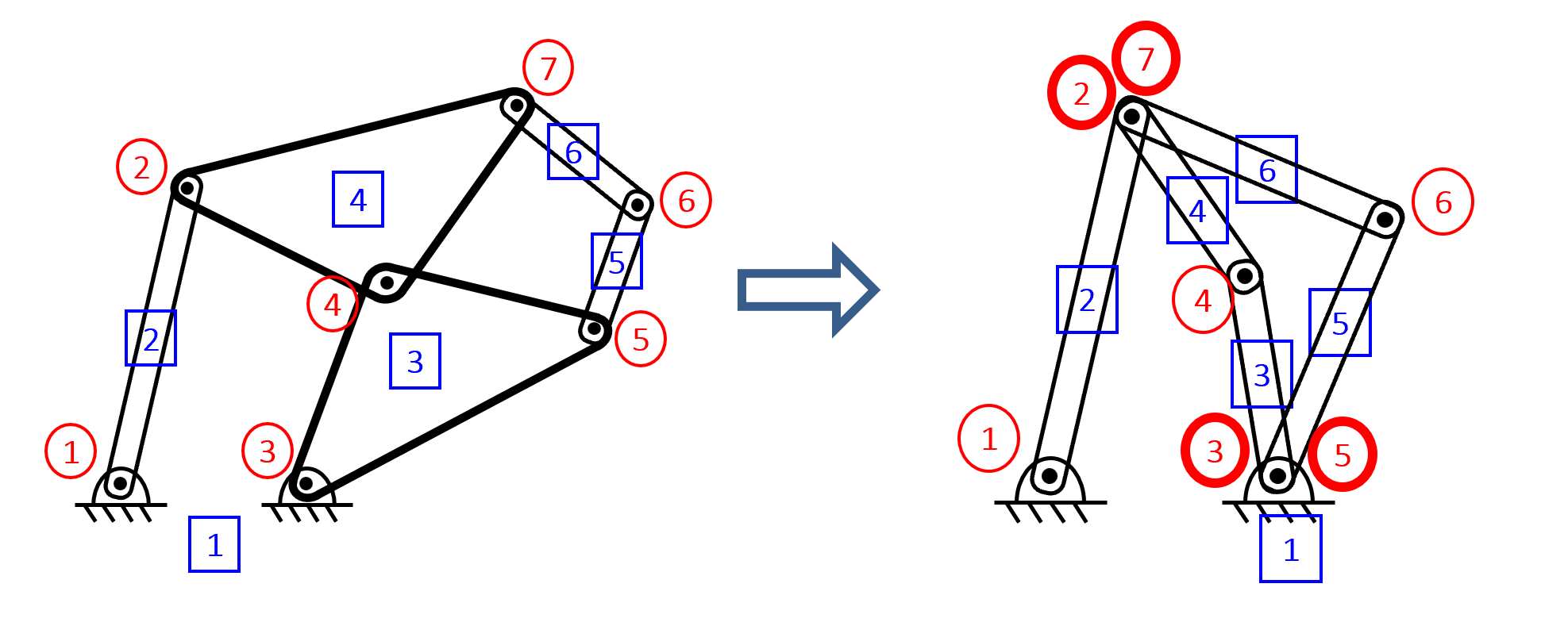
- Combine two nodes. The combination of two nodes maintains the same number of links and joints, so there will be no change in the DOF.
4 bar linkage
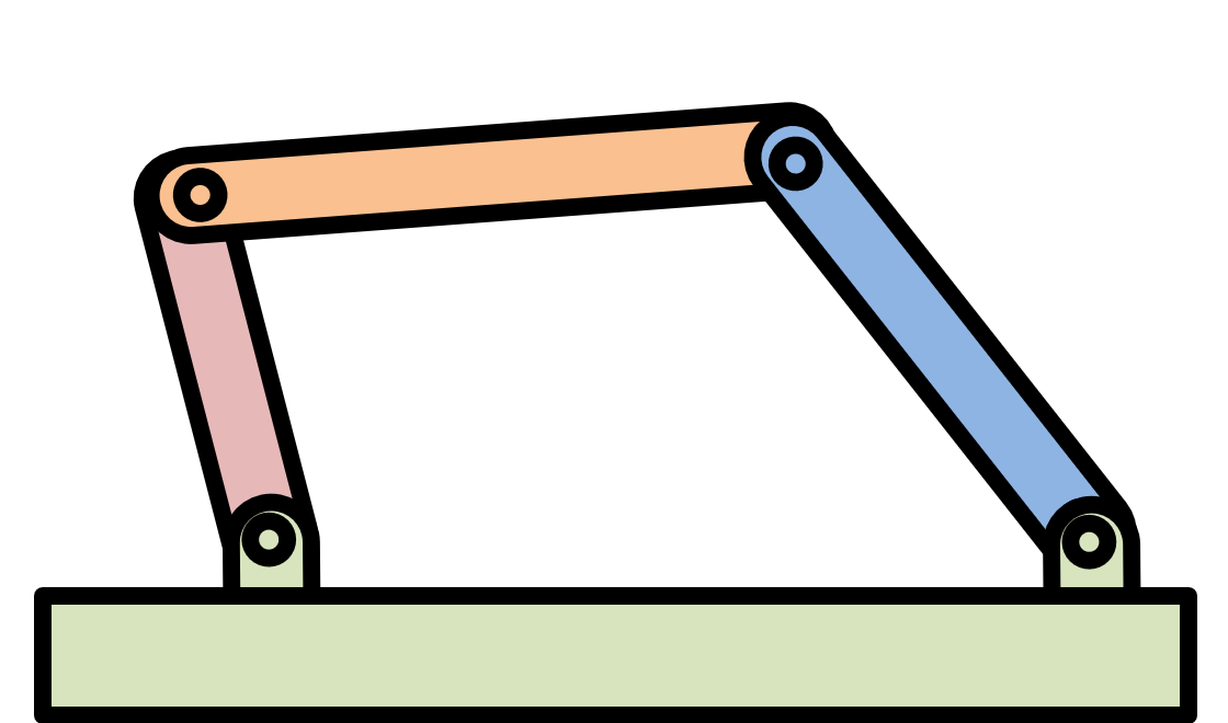
One of the most common mechanisms is a 4 bar linkage. This is because it 4 links connected with 4 full joints is one of the simplest 1 DOF systems.
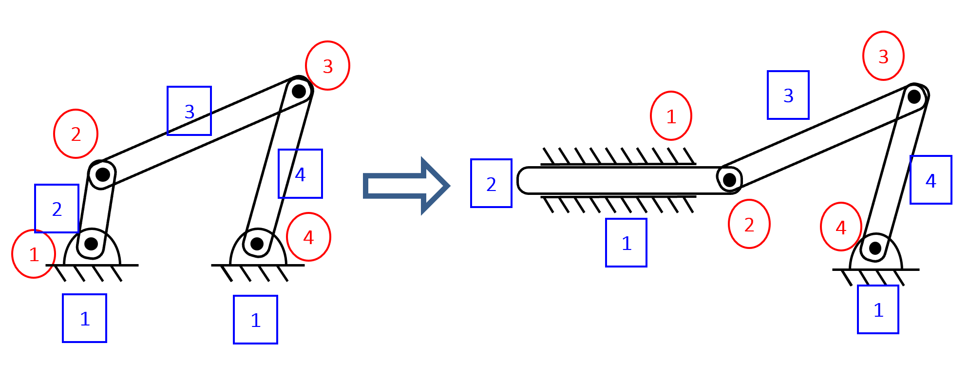
One example of a 4 bar linkage is a crank-rocker where the a rotary input results in an output that rocks back and forth.
Another example 4 bar linkage is a crank-slider, where transformation rule 1 is used to replace the rocker with a sliding joint.
Review?
Need a review of four-bar linkages?
This content has also been in dynamics and has applications.
Grashof Condition
The Grashof condition of a four bar linkage defines the allowed motion of the mechanism. The Grashof condition is determined by the length of the linkages in the four bar linkage, which is then categorized into one of three classes. The shortest link is denoted with the letter \( S \), the longest link with the letter \( L \), and the remaining two links with the letters \( P \) and \( Q \).
- Class 1 (Grashof)
- Class 2 (Non-Grashof)
- Class 3 (Special- Case Grashof)
- Parallelogram: When the two shortest links are opposite to each other, a parallelogram is formed and both of the shortest links make a full rotation.
- Delta: When the two shortest links are adjacent to each other, only one will make a full rotation.
For this classification, at least one link will be able to make a full rotation. If the shortest link is connected to a ground joint, that becomes the crank and will make a full rotation. If the shortest link is the ground, both links attached to the ground will be able to make a full rotation. If the shortest link is detached from the ground completely, the shortest link becomes the coupler and will make a full rotation.
For this classification, no link will be able to make a full rotation as the Grashof condition is not satisfied. There may be some movement in the form of two rockers, but there will be no full rotations.
Similar to Class 1, at least one link will make a full rotation. However, there are two specific forms that the mechanism can take on: