The total mass of a rigid body is as follows:
The center of mass of a rigid body can be calculated as follows:
Finding the center of mass allows us to treat complex shapes as point-masses with all their mass at the center of mass.
To find the center of mass of a body made up of composite shapes, we simply do the weighted average of each body by using the fact above.
Type of shape | Operation |
---|---|
Simple shapes | Symmetry tables |
Combination of simple shapes | Find each c.o.m and then combine |
Complex shapes | Integrate |
The centers of mass listed below are all computed directly from the integral #rcm-cm. Note the center of mass provided is the vector from point \(O\) (the reference origin).
The centers of mass listed below are all special cases of the basic shapes given in Section #rcm-bs. Other special cases can be easily obtained by similar methods, or directly computing the integral.
The moment of inertia of a body, written \( I_{P,\hat{a}} \), is measured about a rotation axis through point \(P\) in direction \( \hat{a} \). The moment of inertia expresses how hard it is to produce an angular acceleration of the body about this axis. That is, a body with high moment of inertia resists angular acceleration, so if it is not rotating then it is hard to start a rotation, while if it is already rotating then it is hard to stop.
The moment of inertia plays the same role for rotational motion as the mass does for translational motion (a high-mass body resists is hard to start moving and hard to stop again).
Observe that the moment of inertia is proportional to the mass, so that doubling the mass of an object will also double its moment of inertia. In addition, the moment of inertia is proportional to the square of the size of the object, so that doubling every dimension of an object (height, width, etc) will cause it to have four times the moment of inertia.
Did you know?
We are always considering the moment of inertia to be a scalar value \( I \), which is valid for rotation about a fixed axis. For more complicated dynamics with tumbling motion about multiple axes simultaneously, it is necessary to consider the full 3 × 3 moment of inertia matrix:
The three scalar moments of inertia from #rem-ec appear on the diagonal. The off-diagonal terms are called the products of inertia and are given by
and similarly for the other terms. The angular momentum of a rigid body is given by \( \vec{H} = I \vec{\omega} \), which is the matrix product of the moment of inertia matrix with the angular velocity vector. This is important in advanced dynamics applications such as unbalanced rotating shafts and the precession of gyroscopes.
One consequence of the parallel axis theorem is that the moment of inertia can only increase as we move the rotation point \( P \) away from the center of mass \( C \). This means that the point with the lowest moment of inertia is always the center of mass itself.
A second consequence of the parallel axis theorem is that moving the point \( P \) along the direction \( \hat{a} \) doesn't change the moment of inertia, because the axis of rotation is not changing as the point moves along the axis itself.
The moments of inertia listed below are all computed directly from the integrals #rem-ec.
The moments of inertia listed below are all special cases of the basic shapes given in Section #rem-sb. Other special cases can be easily obtained by similar methods.
(Assuming that figure is drawn to scale, including velocity vectors)
Consider a car sitting stationary on the ground, as shown below. We will take the entire car plus wheels to be a single rigid body. Clearly this is inaccurate (the wheels can't turn), but it is still useful.
We start with the car stationary, sitting on the road. Gravity acts downward through the center of mass, while there are upwards reaction forces on the wheels and corresponding equal and opposite forces downwards on the ground. Because the car is not accelerating, the total forces on the car are in balance, as we can see on the .
When the driver , this results in the car pushing back on the road, giving a net forward force on the driving wheels (the back wheels for our car), and the car accelerates up to cruising speed. Here we are including air resistance but neglecting rolling resistance, and while cruising at constant speed the driving force exactly balances the drag force from air resistance. When the driver , the car pushes on the road to slow down, giving backward forces on both wheels and causing the car to decelerate to a stop.
Repeat the / cycle a few times while showing the . Observe the horizontal and vertical forces of the road on the car wheels. Also view the forces both in and as total force vectors.
The vertical forces of the road on the car always need to balance the gravitational force, but we can see that the distribution between front and rear wheels changes as the car accelerates and decelerates. This is because the horizontal driving and braking forces are below the center of mass and produce a moment. The vehicle is not rotating, so this moment must be counteracted by the ground forces. The force directions mean that the rear wheels take more weight during acceleration, while the front wheels take more weight during braking.
The maximum force with which the car can push against the road is limited by the friction coefficient of the tire multiplied by the normal force. This applies both during acceleration and braking.
To accelerate as hard as possible, we should thus use a rear-wheel drive layout. If we accelerate too hard, however, then the back wheels will slip and experience wheelspin, because the dynamic coefficient of friction is lower than the static coefficient. While high-performance applications generally want to maintain traction in all cases, the impressive effects of traction loss are sometimes deliberately produced. Spinning the rear wheels in a burnout produces smoke as the tires vaporize due to the heat from friction. Drag racers perform a burnout at the start of a race to clean the tires and heat them to an optimal temperature. To easily produce a burnout a line lock can be installed to enable the brakes to be applied only to the front wheels (although this is often illegal on street cars). Alternatively, a burnout can be performed by disengaging the clutch, running the engine at a high revs, and then rapidly engaging the clutch. The high angular momentum of the engine then provides a rotational impulse to the rear wheels, causing them to lose traction.
Even if traction is maintained during acceleration, a second problem that may occur is that the torque from the rear wheels can be enough to lift the front wheels off the ground, so that the vehicle performs a wheelie. This occurs very easily for motorbikes and BMX bicycles, due to a high center of mass to wheelbase ratio, but can also occur for cars with poor geometry and sufficient power.
The problems of wheel slip and wheel lift-off occur in reverse while braking. Any car with well-maintained brakes has sufficient braking power to cause the wheels to lock, even in dry conditions with good traction. For this reason many cars now include anti-lock braking systems (ABS), which detect wheel locking and rapidly pulse the brake force to prevent locking. Even better than this are electronic brakeforce distribution (EBD) systems, which apply the maximal brake force to each wheel while maintaining traction and control, better than any unassisted human driver could achieve. Due to the weight transfer to the front wheels during braking, the front brakes generally apply much greater force and thus wear out sooner than the rear brakes.
Did you know?
Using ABS to mean Anti-lock Brake System is an example of a backronym. This is where the name ABS came first, and then Anti-lock Brake System was made up later to fit the letters as an ackronym. In fact ABS comes from the German phrase Antiblockiersystem (literally: Anti Locking System).
To understand how forces and moments act on the wheels, we need to separate out the single rigid-body model into multiple rigid bodies. The simplest version of this has one rigid body for the body, and four rigid bodies for the wheels. We will assume that the two front wheels always act as a pair (same forces, same motion), and similarly for the two back wheels.
Again we start with the car stationary, and on the we see the balance of vertical forces. Remember that the force shown on each wheel is really doubled, as there are two front and two rear wheels.
If we now , then we see a clockwise moment applied to the rear (driving) wheels. This causes the wheel to rotate, but friction forces means that it must roll without slipping, so there must be a forward contact force causing it to accelerate forwards. Counteracting this is a backwards reaction force from the car on the wheel. On the car we see that there are equal and opposite forces and moments at the axles. Just as in the single rigid body case, we have a net horizontal force causing forward acceleration, and moment balance means that the weight of the car is transferred primarily to the rear wheels.
applies backwards moments to both wheels, causing them to slow down. To maintain non-slip, there is a backwards force from the ground at the point of contact. Because the wheel is slowing down, the car pushes forward on the axle. The ground/axle forces are trying to rotate the wheel forward, which must be counteracted by the braking moment. The braking moment is thus counteracting both the rotational inertia of the wheel, as well as the force couple from the ground/axle forces. Of these, the force couple is much larger (stopping a wheel without the car attached would be comparatively easy for the brakes). During braking we see again the weight being transferred to the front wheels.
While we can learn a lot about car performance from the simple rigid body and multi-body models, there is a great deal of physics neglected by these models, which can be important for engineering design.
Both the car and the tires are deformable bodies. The deformation of the tire is responsible for the contact patch which generates the friction forces that allow a car to accelerate and brake. The physics of the frictional contact between the tire and ground can be very complex, as can the geometry of the tire. Modern tires have complex tread patterns with grooves and lugs that are designed to channel away water and snow, maintaining traction even in challenging conditions.
As well as being individually deformable, the wheels are are not rigidly connected to the car body as above, but they are actually connected by a suspension system, consisting of linkages, springs, and shock absorbers. These enable both a comfortable ride and safe handling of the vehicle.
The simple models above included a simple model of air resistance, but they neglected rolling resistance. This is the force primarily produced by the tire being compressed and re-expanded at the contact with the ground as it rolls, producing a backward force on the wheel. Using steel wheels on steel can result in trains having up to ten times lower coefficients of rolling resistance than car tires, which is one reason for the efficiency of rail transport.
Did you know?
There is evidence that the wrinkling of fingers in water may serve the same purpose as tread patters on tires, improving traction in wet conditions by forming channels to carry away water. This hypothesis is supported by the fact that finger wrinkling relies on an active nervous system response, meaning that the fingers of corpses cannot wrinkle (but what about zombies' fingers?).
The above model shows equal brake force applied on the front and rear wheels. This both inefficient and dangerous, as the rear wheels will lock while the front wheels are still turning. See #avs for steering and sliding. We want to apply more force on the front brakes, so that we can deliver the most total force while still having no sliding. This can be achieved by electronic brakeforce distribution (EBD) systems, however traditional systems are also possible.
The basic outline of a brake system is that the brake pedal pushes on a master cylinder, which compresses hydraulic brake fluid in the brake lines. This then pushes on slave cylinders in each wheel, which push the brake pads onto the brake rotors (for disc brakes; drum brakes are somewhat different). The combination of slave cylinders and brake pads and their housing is called a brake caliper.
To apply more force to the front brakes, one simple system used in practice is to have the front-wheel slave cylinders have a larger diameter than those on the rear wheels. Because the pressure in the brake lines is the same everywhere, the force exerted by the pistons is proportional to their cross-sectional area, resulting in more force with the larger-diameter front-wheel cylinders.
Modern cars use more advanced systems. The master cylinder typically contains two pistons in a parallel arrangement, so that it can apply pressure to the front or rear brake lines even if the other brake line develops a leak. A metering valve applies pressure to the rear brakes before the front, improving vehicle steering stability and allowing mixed drum/disc systems to be used. A pressure differential valve detects brake hydraulic leaks by sensing different front/rear line pressures. A proportioning valve assists with applying a different pressure distribution to the rear brakes.
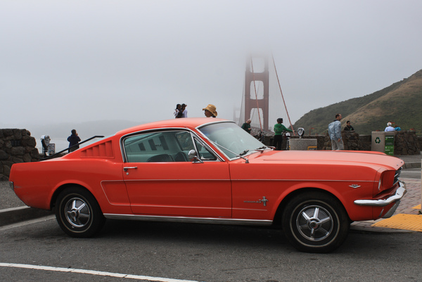
This is a 1965 Ford Mustang Fastback. The mass of the car body is 1100 kg and each of the wheels has mass 20 kg, giving a total mass of 1180 kg. We assume that the wheels are uniform cylinders. The dimensions of the car are shown below.
|
|
The force of air resistance was computed above using the quadratic drag equation which is a good approximation for medium- to high-velocity motion in air:
\( F_{\rm D} = \frac{1}{2} \rho v^2 C_{\rm D} A \)
Here \( F_{\rm D} \) is the drag force, \( \rho = 1.23\rm\ kg/m^3 \) is the air density, \(v\) is the velocity, \( C_{\ D} \) is the drag coefficient (taken to be 0.3 for the Mustang), and \(A\) is the reference area (approximately the cross-sectional area, taken to be \(2.2\rm\ m^2\) for the Mustang).
Complete in "Banked turns". Include all the information starting at "2D rigid body model".
Refer back to \ref sub:PartKin_turnsWe now use a single rigid body model for the bus and we will do everything in 2D. Below we see a front-on diagram of the bus, with the inside of the track to the left. If we turn on the , then we see that the weight of the bus is supported by two forces, one on each wheel. If we increase \(\theta\) then the weight is supported more by the down-slope wheel, and we also see sideways friction forces appear to stop the bus from sliding. If the slope becomes too steep, then the normal force on the up-slope wheel reverses direction, indicating that it is holding the wheel down onto the road. Physically this cannot happen, so at this point the bus would tip over. We needed this rigid-body model to understand this tipping behavior, as we couldn't model this with the point mass model. Depending on the value of the friction coefficient, the bus may either slide or roll first as \(\theta\) increases.
Road bank angle: \(\theta = \) 45\(^\circ\)
Bus speed: \(v = \) 30 \(\rm m/s\)
If we now set the bank angle \(\theta\) back to zero, we can start to increase the speed \(v\). Now we see that the wheel on the inside of the track takes less of the weight, and the friction forces now stop the bus from sliding outwards on the track. If the bus goes too fast then it will roll outwards on the track (assuming the friction coefficient is high enough that it didn't slide first).
Having considered both a banked road with stationary bus, and a moving bus on a horizontal road, we can now combine them to see the advantage of having a banked road when the bus is cornering. Choose a bus velocity, and then change the bank angle \(\theta\), so that the friction force is reduced (helping to avoid sliding) and the normal forces on the wheels are more evenly balanced (helping to avoid rolling). For any given speed, we can choose a bank angle so that there is simultaneously no sideways friction force and also exactly balanced normal forces. This is the safest bank angle for this speed.
A straight road generally has the center somewhat higher than the edges to allow water to run off. This is called cross slope or camber. When it is desired to have a banked turn, then the outer edge of the road is raised to produce superelevation, with the outer edge rising above both the center and the inner edge. The bank angle is chosen based on the radius of curvature of the turn and the expected speed of cars going around the turn, while still allowing for the fact that cars might be moving slowly or even stopped. The angle should thus not be chosen to eliminate all friction forces when cars are traveling at maximum speed, as this would be dangerous if traffic had to stop on the road.
Velodromes are arenas with tracks designed for high-speed bicycle races, as shown below, with speeds up to 85 km/h. The bank angle on velodrome tracks is chosen to minimize sideways forces on the bicycles when they are traveling at near maximum speeds, so the angle chosen depends on the radius of curvature of the track corners. For example, the Blaine velodrome track pictured below is 250 m long and has a 43° bank angle on the corners and 15° banking on the straightaways.
Bicycle riders on a banked turn at the Blaine velodrome, part of the National Sports Center in Blaine, Minnesota. Image source: flikr user flyinfoto (CC BY 2.0) (full-sized image).
High-speed trains such as the French TGV operate at speeds of over 300 km/h and have run at up to 575 km/h. To accommodate cornering at such speeds, track bends are constructed with a large radius of curvature (at least 7 km for new tracks) and a bank angle of up to about 7° (180 mm maximum superelevation with Standard gauge of 1435 mm). For railways, banking the track is know as cant.
An alternative approach for cornering with trains is to leave the track relatively flat and to tilt the train as it travels around a corner. This allows high-speed trains to operate on regular tracks, while maintaining safety and comfort for the passengers. For example, the Queensland Rail Tilt Train operates at 180 km/h by tilting at up to 5° around corners. As we see from our rigid body analysis above, tilting the train will help with avoiding tipping over at high speeds, but will not help with reducing horizontal friction forces. Even with a tilting train, entering a curve at too high a speed will lead to disastrous results.
Did you know?
The Blaine velodrome in Minnesota was designed by the famous Schuermann velodrome architects and built from the extremely durable African Afzelia hardwood. Velodrome races are always counter-clockwise and use special bikes with fixed chains (no freewheeling, no gears) and no brakes. The corners are scarily steep:
Did you know?
High-speed trains such as the French TGV and German ICE require many sophisticated engineering techniques to enable travel at extreme speed. Very smooth rails are needed, so the track is formed by welding the segments together into one precisely-aligned continuous steel line. The steel rails conduct heat too well for conventional welding, so thermite welding is used to join the track segments.
At high speeds the train drivers are unable to see railway signals on the side of the track. Electronic signaling systems are used to communicate to the drivers, either through the tracks for the TGV or via additional cables for the ICE.
Friction-based brakes produce too much heat, as they would need to absorb the kinetic energy of several hundred tonnes of train moving at over 300 km/h. Instead, dynamic breaking is used, in which the electric motors powering the trains are run in reverse as generators and the energy is shed as heat in resistor arrays. At extremely high speeds, the wheels themselves cannot provide sufficient traction to enable braking, so technologies like magnetic induction brakes are being developed, which directly push against the rails without involving the wheels at all.
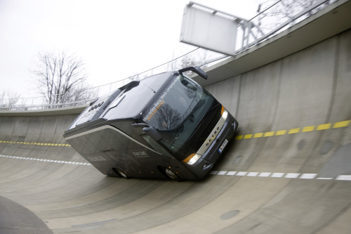
The bus model used above is a Setra S 411 HD coach. The mass of the vehicle is 12.6 t and the dimensions are shown below.
|
|
This topic is in L22-Notes, slides 3-4.
Application for "Center of mass".This topic is in L24-Notes, slide 9. YouTube video link
Application for "Rigid body kinetics".