Trusses
Trusses composed of long, slender support members that are joined together at the ends with pins. The function of a truss is to transmit loads to a support joint. In this section, we will analyze a simplified version of planar trusses called simple trusses, which consist of two-force members connected by frictionless joints/pins.
Truss assumptions
The main assumptions for trusses and truss structures are:- All loading is applied at the joints.
- The joints are frictionless.
- The weight of the truss is negligible.
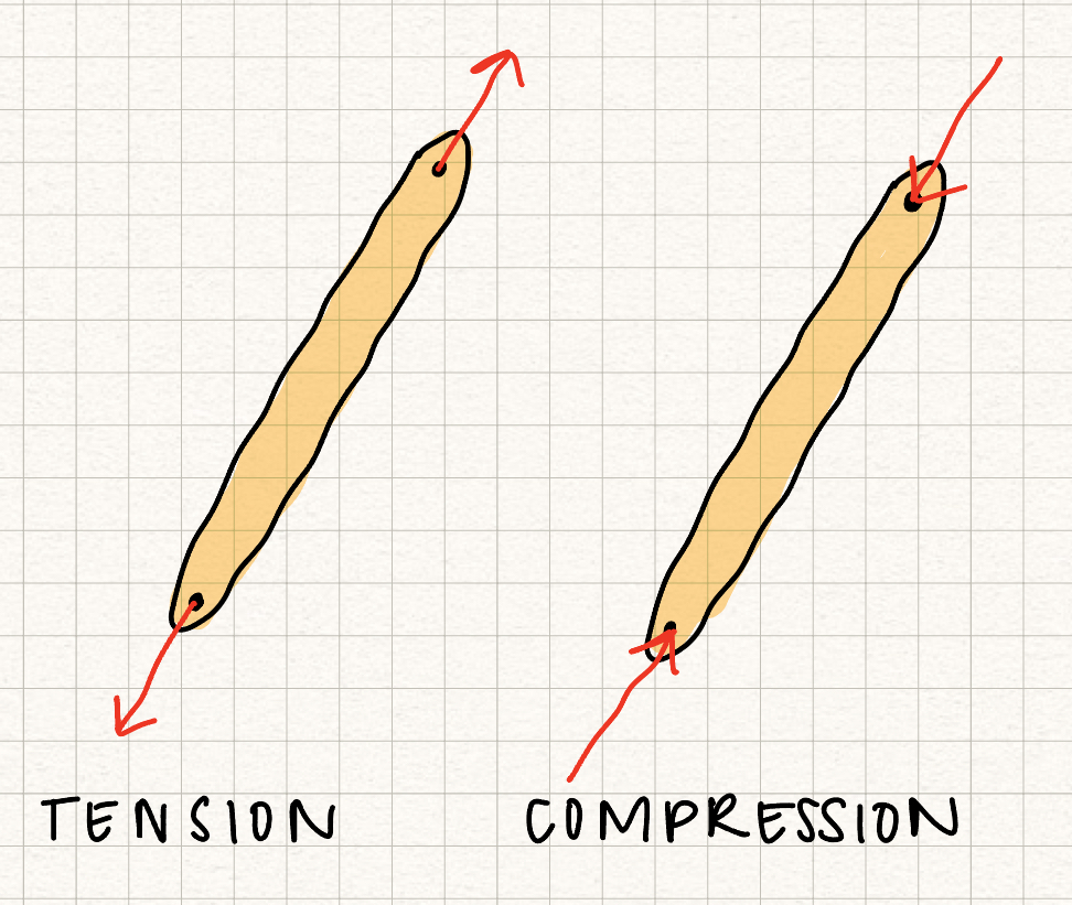
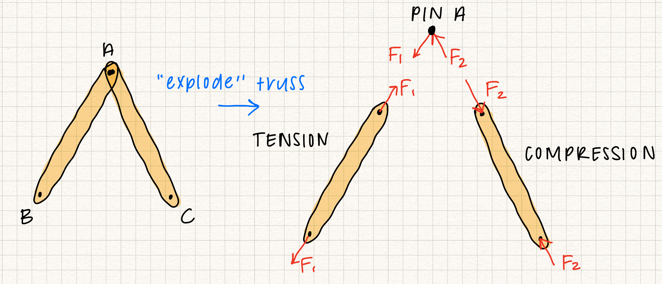
Because of these assumptions, all truss members are two force members, with the forces on the truss acting along the axis of the member. If the forces on the truss member "stretch" it, the member is in tension. If the forces on the truss member "squish" it, the member is in compression. In our class, we'll assume that members are always in tension. If we solve for the force in a member and get a negative number, we know that member is actually in compression.
Review?
Need a review of vector representation in FBDs?
This content has also been explained earlier in the course.
Two force member
A two force member is a rigid body that has two forces (no moments) acting on it in two locations, say \(A\) and \(B\). Equilibrium of the two-force member implies
- \(|F_A| = |F_B|\)
- \( \vec{F_A} \) and \( \vec{F_B} \) act along the same line of action.
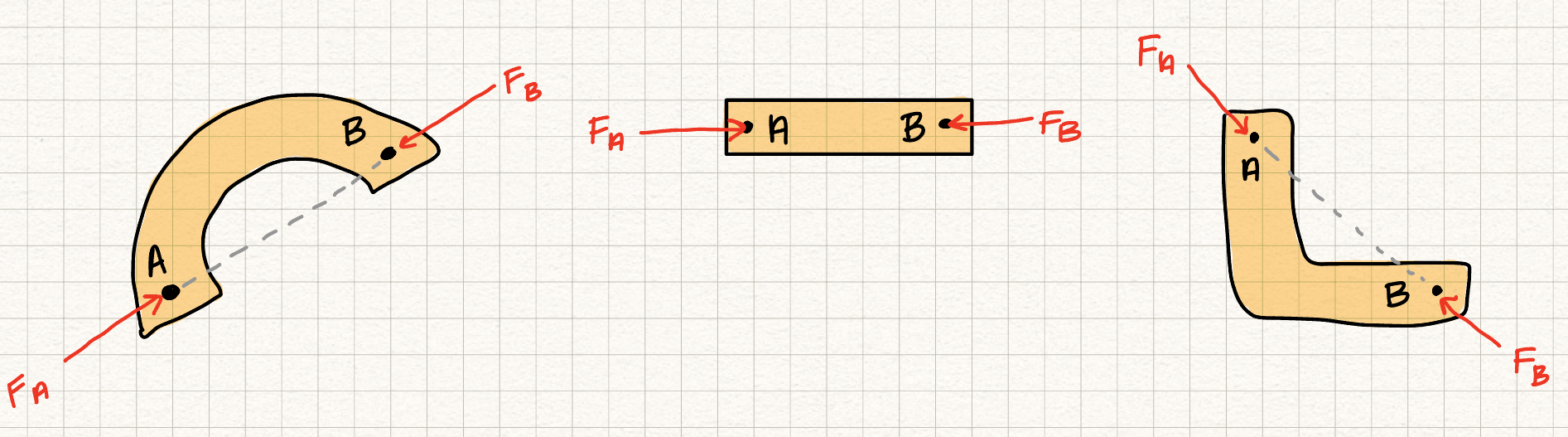
Specifically, the two forces act along the line between the two points where they are applied.
Zero force member
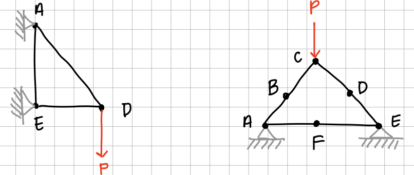
Zero force members are members in a truss structure that experience no force. They act as support trusses to add stability, but are not load bearing. There are 2 cases where zero force members occur:- Two noncolinear members share a pin with no support or external forces; the two noncolinear members are zero force members (Zero force member example, left - look at pin \( C!) \)
- Two colinear members with a third noncolinear member on a pin with no support or external forces; the third noncolinear member is a zero force member (zero force member example, right - look at pins \( B \) and \( D!) \)
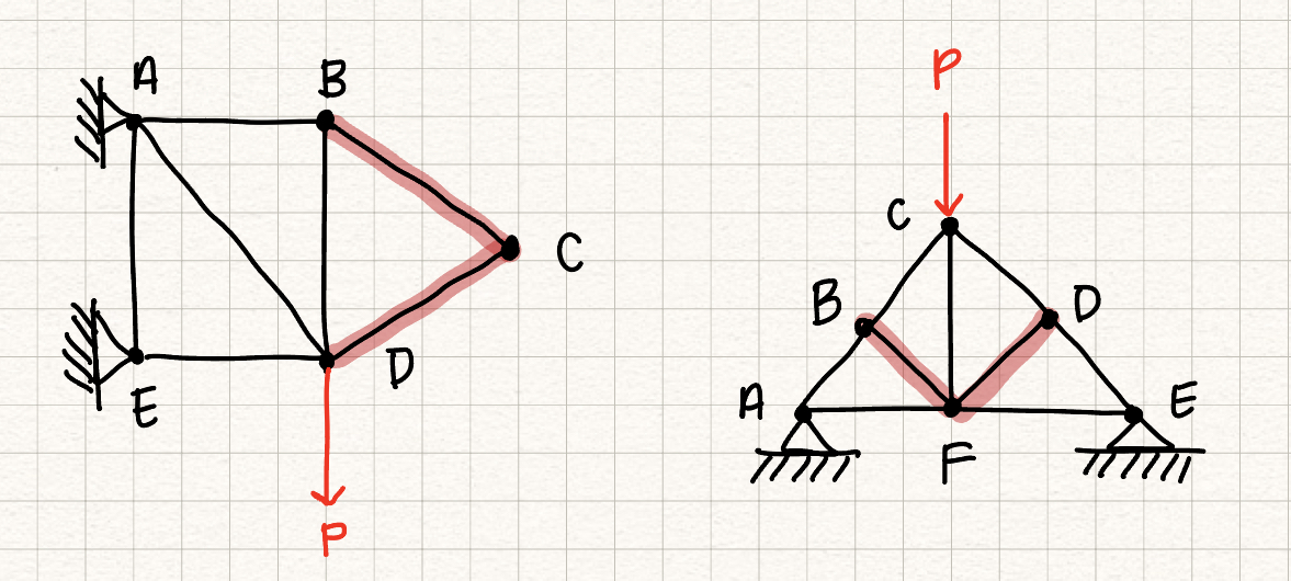
In the left truss, member \( BC \) and member \( CD \) are two noncolinear members that share a pin with no support or external forces, so \( BC \) and \( CD \) are zero force members and are removed.
In the right truss, member \( AB \) and member \( BC \) are two colinear members and member \( BF \) is a third noncolinear member on a pin with no support or external forces, so member \( BF \) is a zero force member and is removed. Similarly, member \( CD \) and member \( DE \) are two colinear members and member \( DF \) is a third noncolinear member on a pin with no support or external forces, so member \( DF \) is a zero force member and is removed.
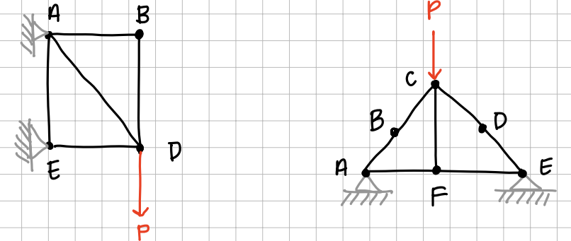
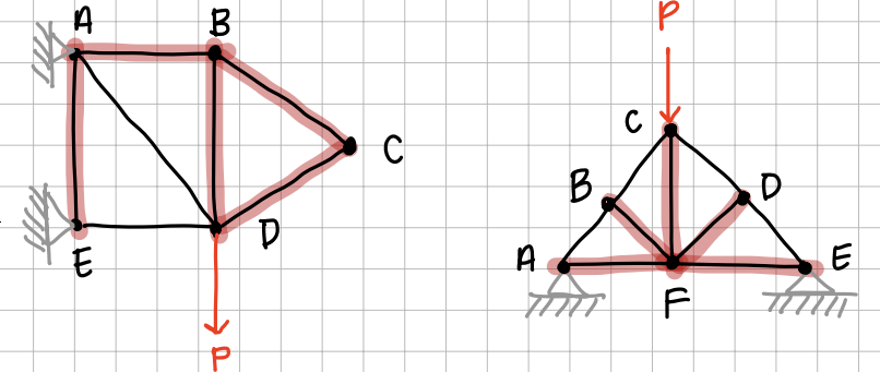
In the left truss, member \( AB \) and member \( BD \) are two noncolinear members that share a pin with no support or external forces, so \( AB \) and \( BD \) are zero force members and are removed.
In the right truss, member \( AF \) and member \( EF \) are two colinear members and member \( CF \) is a third noncolinear member on a pin with no support or external forces, so member \( CF \) is a zero force member and is removed.
It should be noted that not every zero force member was found using the two cases.
In the left tuss, member \( AE \) is a zero force member because it is between two pin supports.
In the right tuss, member \( AF \) and \( FE \) are zero force members because they are between two pin supports.
The following image shows every zero force member identified after a complete analysis is carried out.
These rules will help us simplify trusses and solve for the internal forces in the desired members. It should be noted that these rules will not always identify every zero force member in the truss. Additional analysis may be needed.
Drawing free-body diagrams on trusses is simple. As mentioned in the beginning, we will choose the entire truss as our system and draw the free-body diagram to determine the reaction forces on pinned/roller joints. Note we will need more equations and free-body diagrams on individual truss members to fully determine the reaction forces. The following is a diagram showcasing eliminating zero-force members.
Truss analysis: method of joints
Method of joints for truss analysis:- Draw a free-body diagram for the entire truss and solve for the external reaction forces and moments at the supports
- Draw a free-body diagram of a joint with at least 1 known force and at most two unknown forces
- Use the equations of equilibrium for the joint to solve for the unknown forces
- Repeat steps 2 and 3 to find the forces in the trusses you are interested in.
Note: Remember that truss members that are in compression "push back" on the pin joints, and truss members that are in tension "pull" on the pin joints.
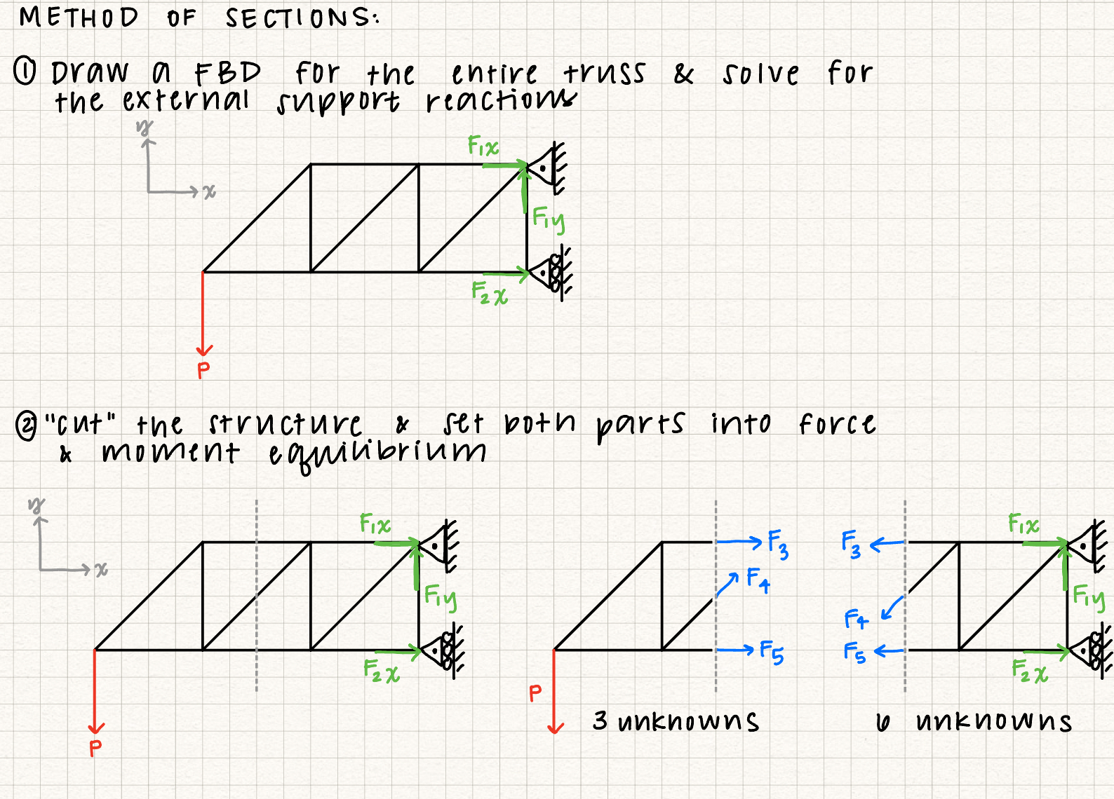
Truss analysis: method of sections
The method of sections is helpful for determining the internal forces inside a truss member. The first step for the method of sections is the same as the firts step for the method of joints: Draw a FBD for the entire truss and solve for the external forces at the supports. Then, you "cut" the truss so that the internal force you want is "exposed" from the cut and analyze the two parts of the truss system to solve for the internal forces of the truss members.
Truss Determinacy and Stability
Determinacy and stability are important concepts to understand when analyzing trusses. These concepts are related, but not the same.
Review?
Need a review of system classifications?
This content has also been explained earlier in the course.
Determinacy
Determinacy is defined as whether or not a structure's internal forces can be determined using only the equations of equilibrium.
Stability
Stability is defined as a truss's ability to maintain overall equilibrium under load. Stability is not the same as determinacy. Unstable structures should always be avoided. If a structure is unstable, do not bother to discuss determinacy.
Procedure
To determine the determinacy and stability of a truss, follow the folllowing procedure.
| Determinacy | Stability | |
|---|---|---|
| \( b + r < 2 j \) | (determinacy is only meaningful when a structure is stable) | Unstable |
| \( b + r = 2 j \) | Determinate | Possibly stable, but depends on configuration |
| \( b + r > 2 j \) | Indeterminate |
In the relation, \( b \) is the number of members, \( r \) is the number of reactions, and \( j \) is the number of joints. \( b + r \) is the number of unknowns and \( 2 j \) is the number of equations. If the stability depends on the configuration, check for improper constraints and internal collapse mechanisms. The following are some examples of improper constraints.
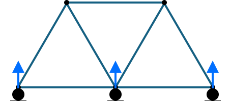
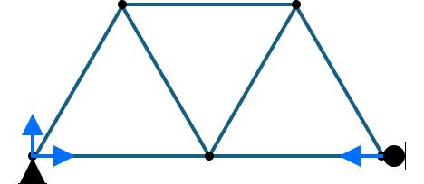
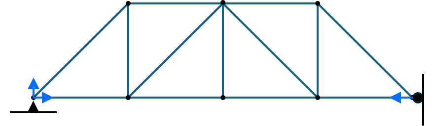
If all reactions are parallel like in that of the first example, then the truss will be able to move in the \( x \)-direction. If all reaction forces are concurrent at one point (e.g., the left pin joint), no restoring moment can be generated about that point, which leads to instability.
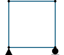
Squares (and rectangles) are common examples of internal collapse mechanisms. The geometry (internal angles) of these shapes can change without the member lengths changing, causing instability.
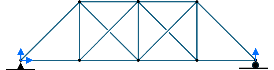
Is the truss determinate?
Is the truss stable?
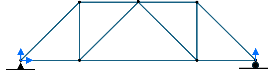
The truss is determinate and stable due to no improper constraints or internal collapse mechanisms.
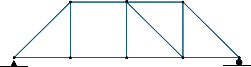
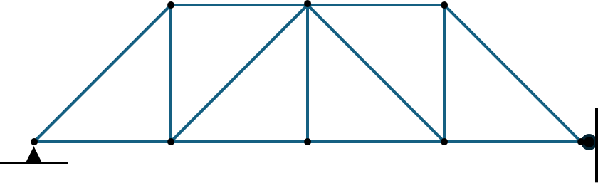
Is the truss determinate?
Is the truss stable?
The truss is unstable, internal collapse mechanism.
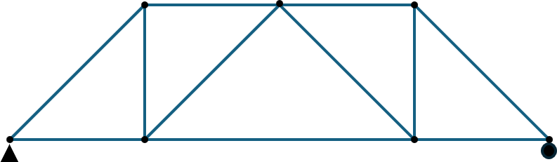
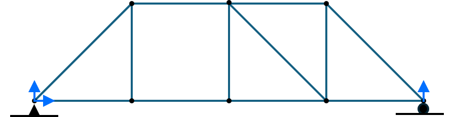
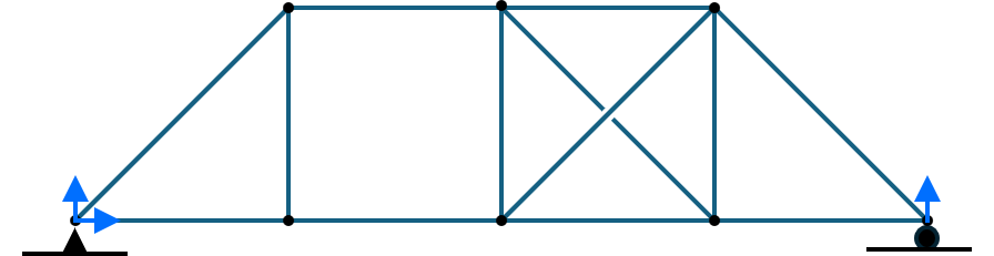
Is the truss determinate?
Is the truss stable?
The truss is indeterminate and stable due to no improper constraints or internal collapse mechanisms.
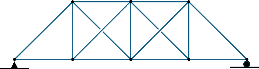
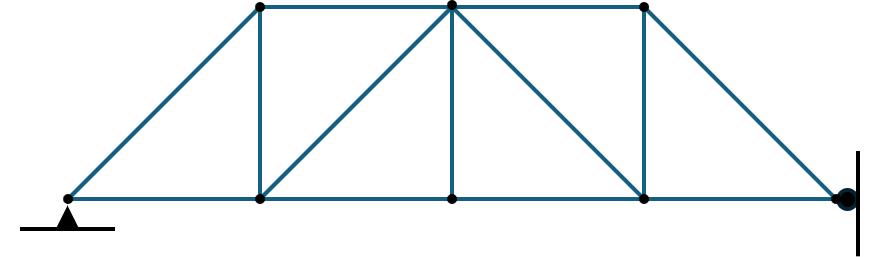
Is the truss determinate?
Is the truss stable?
The truss is unstable due to an internal collapse mechanism. The equation would indicate that the truss is determinate, but because the truss is unstable, determinacy is not meaningful.
Is the truss determinate?
Is the truss stable?
The truss is unstable due to improper constraints, all reactions concurrent at one point. The equation would indicate that the truss is determinate, but because the truss is unstable, determinacy is not meaningful.