Balancing
We normally treat the ground as an immovable object when considering the forces that mechanisms might apply to it. However, in practice this is not always the case. For many mechanisms, it is advantageous to try to minimize the forces and moments that are applied to the ground.
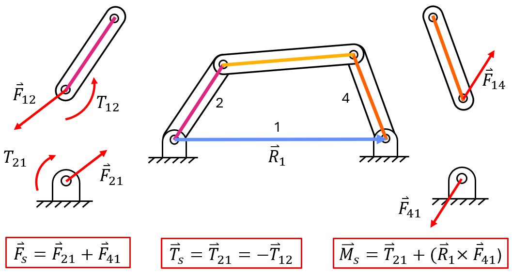
Shaking force (\( \overrightarrow F_s \)) is the total force acting on the ground plane. Similarly, shaking torque (\( \overrightarrow T_s \)) is the reaction torque and shaking moment (\( \overrightarrow M_s \)) is the total moment both of which are felt by the ground plane. These shaking forces and moments often occur in rotating machinery and mechanisms such as gas turbines, electric motors, and piston engines. This shaking can cause vibration, noise, failure, and more in a given system.
To balance a system, it is assumed that there are no unbalanced forces due to external forces or gravity, as it is difficult to balance these things. Instead, we work to balance the internal forces that come from accelerating a body's center of mass.
Balancing is achieved by adding some small balancing masses to reduce or eliminate the net forces and moments. This does not eliminate these loads, but rather adds additional forces to counteract these so that the net load is zero.
Balancing Applications
When mechanisms are unbalanced, they often fail, sometimes catastrophically
Washing Machine vs Brick
Spinning Lego Wheels FAST
''Single Plane'' Balance
Consider the pin joint in the figure below. The angular momentum is constant, so there is no torque acting on the pin joint. The forces on this pin joint come from accelerating the center of mass of a crank so that it moves in a circle. This cyclical loading can cause fatigue or change the behavior of the motor.
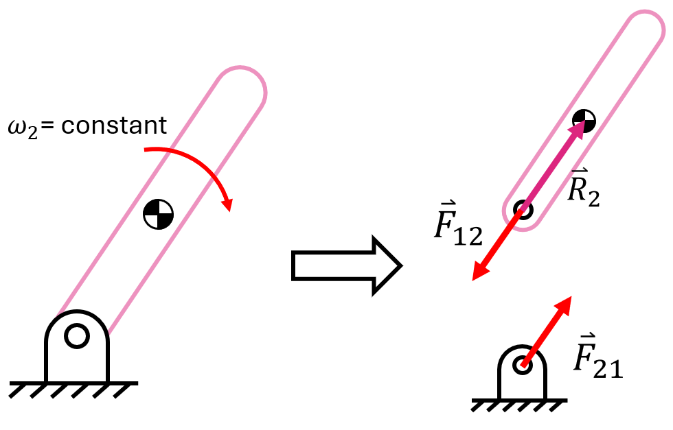
This force is:
To eliminate it, we have a few options:
- Reduce \( m_2 \) to \( 0 \). This is not realistic, as the linkage would no longer exist.
- Reduce \( \omega_2 \) to \( 0 \). This means that our mechanism cannot move, which defeats its purpose.
- Reduce \( \overrightarrow R_2 \) to \( 0 \). This is feasible. We just need to move the center of mass to align with the axis of rotation.
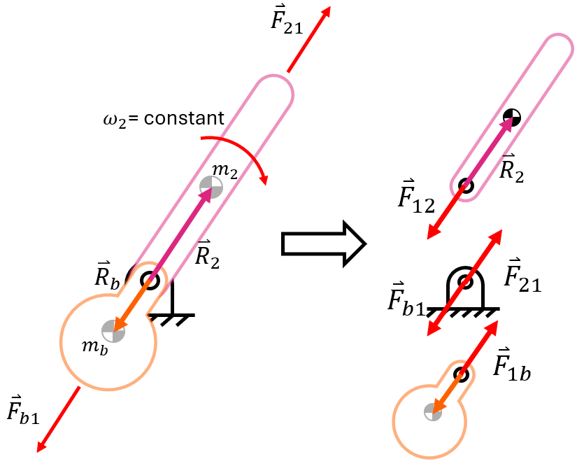
To do this, we need to add an additional mass to move the center of mass. We will call this ``mass b'' to represent the balancing mass.
Recall that the center of mass is:
Since we want the center of mass to be located at the position of the axis, we can make the axis the origin. This means that the balancing mass \( m_b \) and the balancing distance \( r_b \) should fulfill
Essentially, we need the sum of the masses times their distance from the axis to be 0. This will result in no net inertial force on the pin joint. We also note that we have 2 unknowns, \( m_b \) and \( r_b \). However, this is actually a good thing, as it allows for designers to decide whether they prefer a large heavy mass close to the axis, or a smaller one that is further away.
''Two Plane'' Balance
The previous procedure effectively eliminates the forces arising from the rotation of masses in a single plane. However, if all of the masses are not in a single plane, the forces from these masses can cause a moment on the shaft. This leads us to the idea of two plane (or dynamic) balance.
In this case, we add two masses in different planes with the goal of eliminating the net inertial force, as well as the moment arising from these inertial forces.
To compute the moment
Where \( l \) is the position vector along the axis or shaft, whereas \( \overrightarrow R \) is the vector pointing from the shaft to the mass.
Our goal is to make it such that the sum of all of these moments is 0. To do this, set up two different correction planes to put masses in. Take the moment around one plane.
A good example for dynamic balancing is a CT scanner. A CT scanner is composed of many different elements that have to rotate about an axis at a constant rate to get a good image of the person being scanned. For this example, let us simplify the CT scanner and only consider the x-ray source, the x-ray detectors, and the cooling system. Assume the x-ray source and the cooling system as a single point mass located at the center of mass of each system while the x-ray detectors as two point masses as there are more detectors that each have a sizable mass. In this case, the location of the x-ray source and detectors is known because they have to be across from each other to operate properly. Using the cooling system and an extra balance, we can work to balance the system.
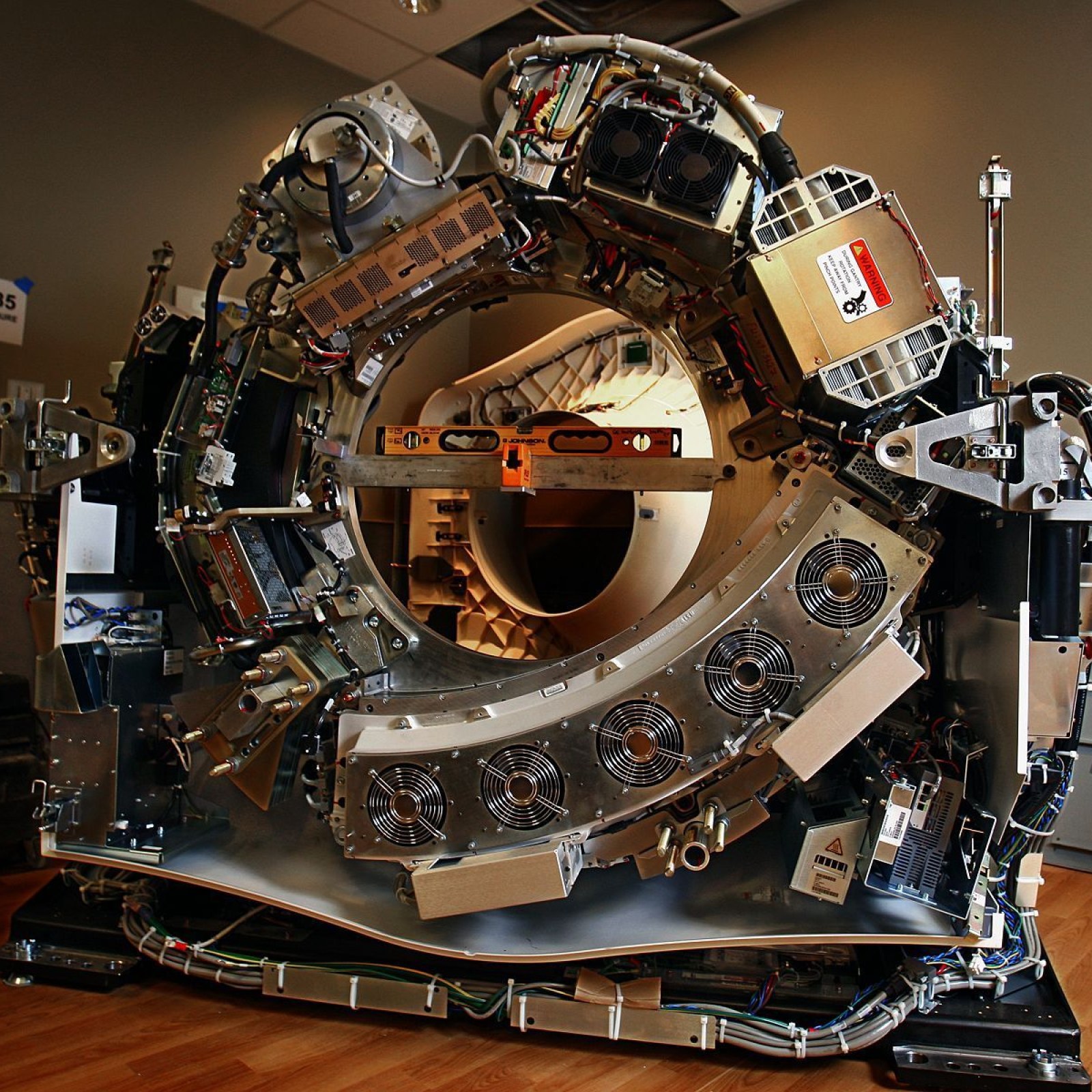
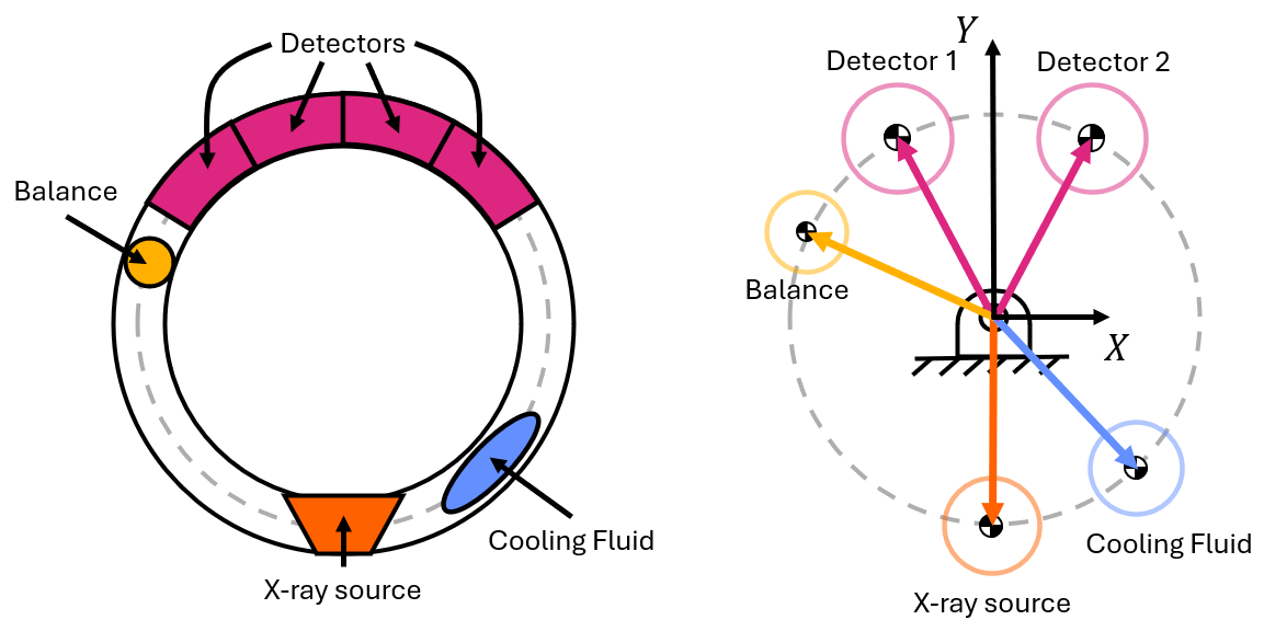
In this example, you are free to decide the mass of the balance and the cooling fluid along with the x- and y-positions of each.
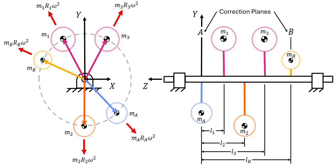
By summing taking the sum of the forces and setting them equal to zero, two equations will result (one with x-components and one with y-components).
X-Component:
Y-Component:
We can also find two more equations by summing the moments about plane A.
X-Component:
Y-Component:
We have six unknowns (two masses, two x-positions, and two y-positions). Again, this is okay because it allows for design freedom.